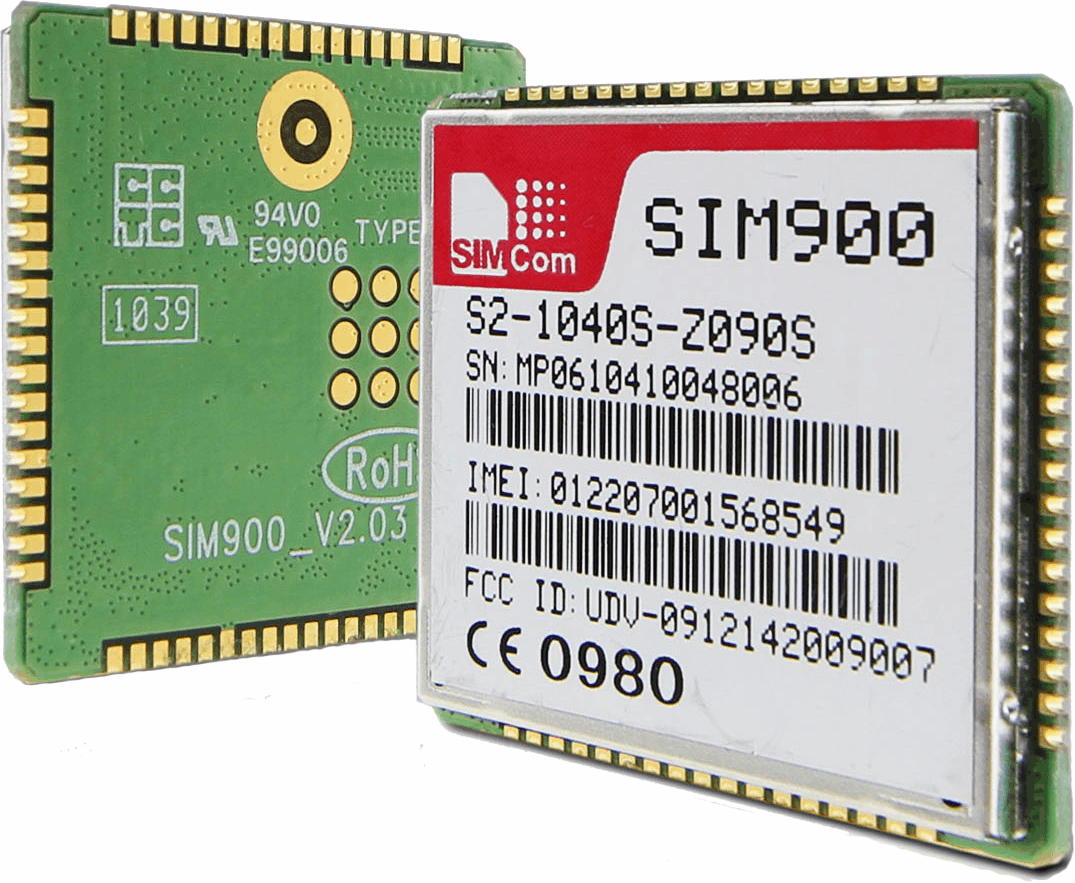
Overview of SIM900A
SIM900 enables GPRS connectivity to embedded applications.
It is widely used in IoT (Internet of Things) embedded applications, where every sensor is connected to a server and we have access to control them over the internet.
The GSM/GPRS module uses USART communication to communicate with a microcontroller or PC terminal. AT commands are used to configure the module in different modes and to perform various functions like calling, posting data to a site, etc.
For more information about Sim900A and how to use it, refer to the topic Sim900A GSM/GPRS Module in the sensors and modules section.
Connection Diagram of SIM900 with MSP-EXP430G2 TI Launchpad
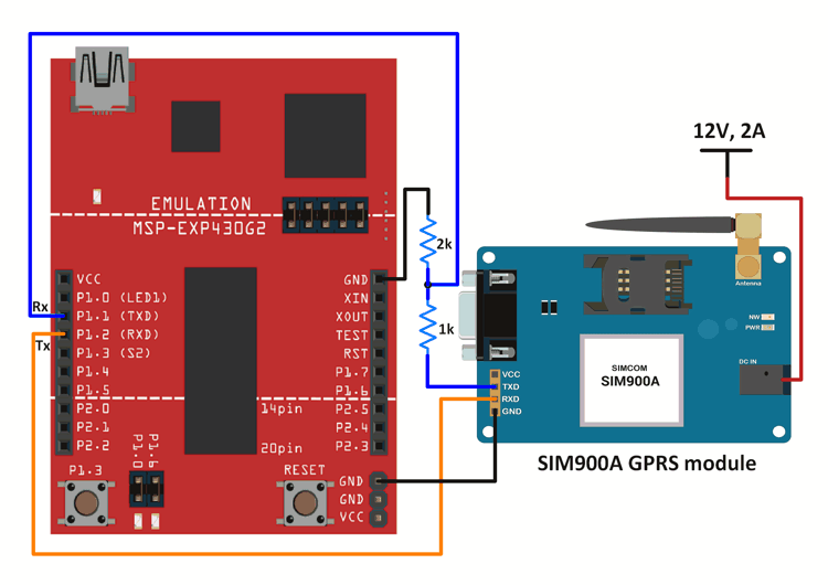
Note: For the TI Launchpad board, P1.1 is the Rx pin and P1.2 is the Tx pin when the jumpers are positioned for using Hardware Serial. Here, we are using, Hardware Serial, hence P1.1 is the Rx pin and P1.2 is the Tx pin.
When jumpers are positioned for software serial, P1.1 acts as the Tx pin, and P1.2 acts as the Rx pin.
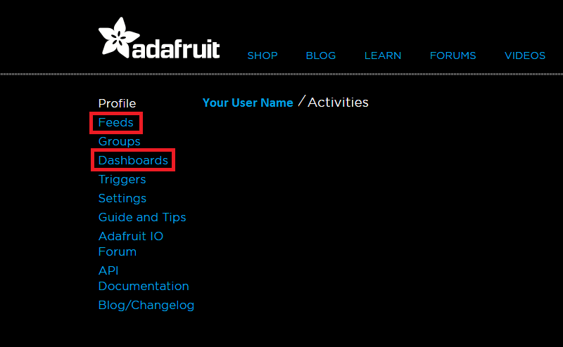
Adafruit IO
Adafrut IO provides an IOT platform where one can create dashboards that respond to the data sent/received from/to the server.
Just sign up to avail of the Adafruit IO services and create your own dashboard.
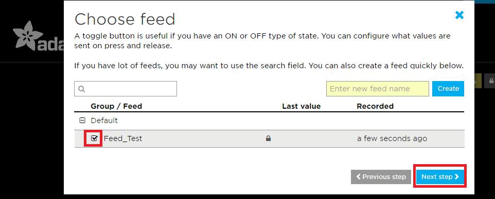
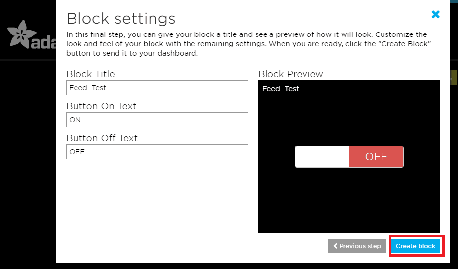
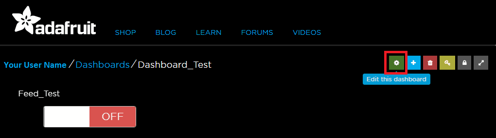
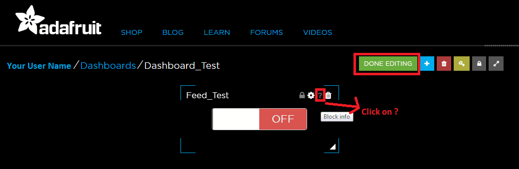
Follow the sequence of images given below to create your own dashboard and a feed linked to it. The images are self-explanatory and easy to understand.
There are various blocks that you can add to the dashboard, we will be using the toggle block for the examples given below.
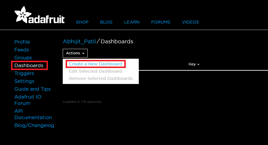
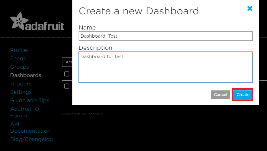
After clicking on create, click on the name of the dashboard from the list.
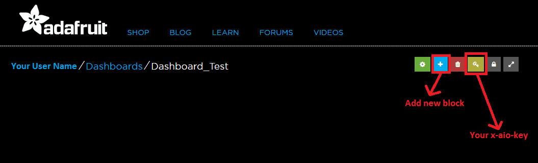
Click on Add new block icon.
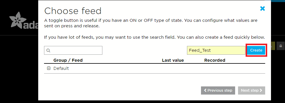
Click on Create.
You can also refer https://learn.adafruit.com/adafruit-io-basics-dashboards?view=all to know more about how to create your dashboard and get started.
Example
- LED control (ON/OFF) through a web server. (GET)
- Sending status of LED (ON/OFF) to a web server. (POST)
Here, we will be using the HTTP GET method for example 1. LED on the Launchpad board will be controlled through the toggle switch on the Adafruit IO website.
For example 2, we will make use of the HTTP POST method. The toggle switch is used to turn ON/OFF LED on the Launchpad board, and the status of the LED is sent to the Adafruit IO server which in turn changes the status of the toggle switch on the dashboard.
We will use Sim900A with a standard SIM card to gain access to the Internet through GPRS.
We will be using the Adafruit IO server.
Create a dashboard with a toggle block as shown in the images above. You may choose the names of your liking for the dashboard and the feed.
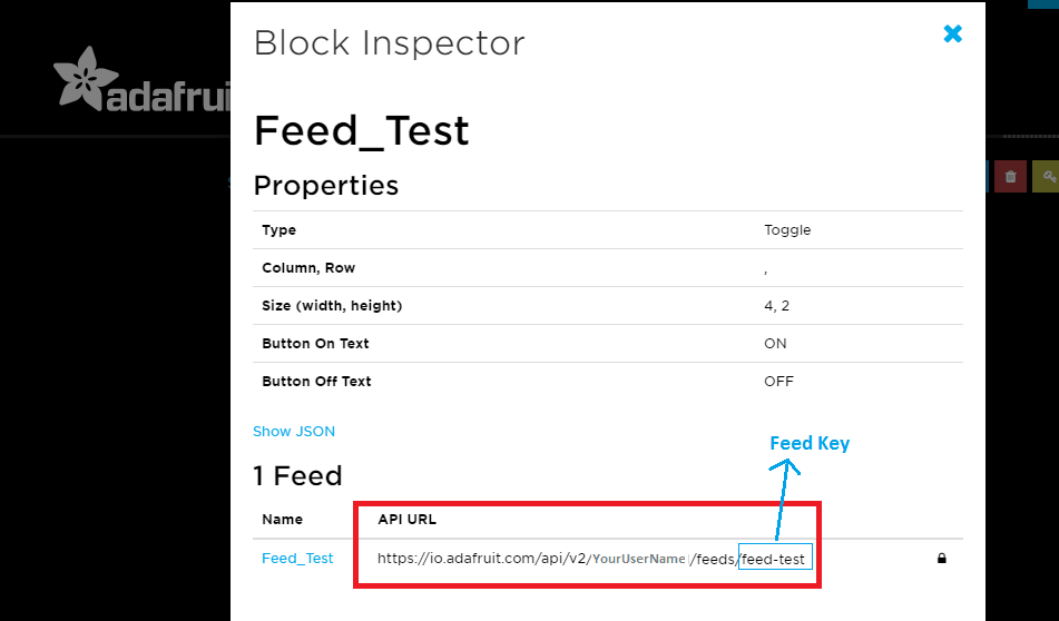
Changes made on the dashboard are reflected in the feed. You can go to the feed page, you will see the values corresponding to the dashboard values (in this case, ON/OFF) over there along with their time stamps.
Now we are ready to POST data to this server and to GET (read) the last data in it.
For POST, we need to use the URL of the format given below :
io.adafruit.com/api/v2/YourUserName/feeds/FeedKey/data? x-aio-key=YourAIOKey
This is followed by data of the format
{"value": "OFF","created_at": "20:00:01","lat": 0,"lon": 0,"ele": 0,"epoch": 0}
Replace OFF by ON if you want to send ON instead of ON.
created_at time doesn’t matter, the server uses its time to figure out the time of arrival. But the created_at value cannot be left 0 like lat, lon values.
For GET, we need to use the URL of the format given below :
io.adafruit.com/api/v2/YourUserName/feeds/FeedKey/data/last?x-aio-key=YourAIOKey
Tread Carefully: MSP-EXP430G2 TI Launchpad board has a RAM of 512 bytes which is easily filled, especially while using different libraries. There are times when you need the Serial buffer to be large enough to contain the data you want and you will have to modify the buffer size for the Serial library. While doing such things, we must ensure that the code does not utilize more than 70% RAM. This could lead to the code working in an erratic manner, working well at times, and failing miserably at others.
There are times when the RAM usage may exceed 70% and the codes will work absolutely fine, and times when the code will not work even when the RAM usage is 65%.
In such cases, a bit of trial and error with the buffer size and/or variables may be necessary.
IOT based LED control Code using GPRS over HTTP protocol for TI launchpad
volatile bool a=HIGH;
volatile bool flag = LOW;

void flush_rx_buffer()	/* Flush out the data in the receive buffer*/
{
  char c;
  while(Serial.available()!=0)
  {
    c = Serial.read();
  }
}

void read_rx_buffer()
{
  int8_t i=0;
  char rx_buffer[90];
  memset(rx_buffer,0,90);
    while(Serial.available()!=0)  /* If data is available on serial port */
    {
      rx_buffer[i] = Serial.read(); /* Copy received data to buffer for later use */
      i++;
    }
  if( strstr(rx_buffer, "\"value\":\"OFF\"")!=0 )	/* If status of switch at server is OFF */
  {
    digitalWrite(2, LOW);	/* Turn OFF the LED1 */
  }
  else if( strstr(rx_buffer, "\"value\":\"ON\"")!=0 )	/* If status of switch at server is ON */
  {
    digitalWrite(2, HIGH);	/* Turn ON the LED1 */
  }
  else
  {
    digitalWrite(14, a);	/* Toggle LED2 if neither ON or OFF received */
    a = !a;
  }
  flag = HIGH;
}


void setup() {
  Serial.begin(9600);	/* Define baud rate for serial communication */
  pinMode(2, OUTPUT); /* LED1 for status of control switch */
  pinMode(14, OUTPUT); /* LED2 for error */
  digitalWrite(2, LOW);
  digitalWrite(14, LOW);
}

void loop() {
  char data[70];
  memset(data,0,70);
  char user[15] = " "; /* Your User Name for Adafruit IO account */
  char feed[10] = " "; /* Name of the feed you created */
  char key[34] = " "; /* Your Adafruit IO key */
  Serial.print("HTTP get method : \n");
  /* Configure bearer profile 1 */
  if(flag == HIGH)
  {
    delay(7000);
    flag = LOW;
  }
  Serial.println("AT+SAPBR=0,1");  /* Close GPRS context */
  delay(700);
  Serial.println("AT+SAPBR=3,1,\"CONTYPE\",\"GPRS\"");  /* Connection type GPRS */
  delay(700);
  Serial.println("AT+SAPBR=3,1,\"APN\",\"TATA.DOCOMO.INTERNET\"");  /* APN of the provider */
  delay(700);
  Serial.println("AT+SAPBR=1,1");	/* Open GPRS context */
  delay(700);
  Serial.println("AT+HTTPTERM");  /* Terminate HTTP service */
  delay(700);
  Serial.println("AT+HTTPINIT"); /* Initialize HTTP service */
  delay(700);
  Serial.println("AT+HTTPPARA=\"CID\",1");	/* Set parameters for HTTP session */
  delay(700);
  Serial.print("AT+HTTPPARA=\"URL\",\"io.adafruit.com/api/v2/");
  sprintf(data, "%s/feeds/", user);
  Serial.print(data);
  memset(data,0,70);
  sprintf(data, "%s/data/last?", feed);
  Serial.print(data);
  memset(data,0,70);
  sprintf(data, "x-aio-key=%s\"", key);
  Serial.println(data); /* Set parameters for HTTP session */
  delay(700);
  flush_rx_buffer();
  Serial.println("AT+HTTPACTION=0");	/* Start GET session */
  delay(7000);
  flush_rx_buffer();
  Serial.println("AT+HTTPREAD");	/* Read data from HTTP server */
  delay(5000);
  read_rx_buffer();
}
Video of IOT based LED control using GPRS over HTTP protocol with TI launchpad
IOT based LED monitoring Code using GPRS over HTTP protocol for TI launchpad
volatile char *switch_state;
volatile bool state;
volatile bool interrupt_flag;

void setup() {
  Serial.begin(9600);			/* Define baud rate for serial communication */
  pinMode(5, INPUT_PULLUP); 	/* PUSH2 switch for changing toggling switch */
  pinMode(2, OUTPUT); 			/* LED for displaying state of switch */
  digitalWrite(2, LOW);
  attachInterrupt(5, control, FALLING);  /* Interrupt on falling edge on pin 5 */
  state = HIGH;
  interrupt_flag = LOW;
  switch_state = (char *)"OFF";
}

void loop() {
  char data[80];
  memset(data,0,80);
  char feed_key[10] = " "; 		/* Name of the feed you created */
  char user_name[14] = " "; 	/* Your User Name for Adafruit IO account */
  char key[34] = " "; 			/* Your Adafruit IO key */
  if(interrupt_flag == HIGH)
  {
    delay(7000);
    interrupt_flag = LOW;
  }
  Serial.println("HTTP post method :");
  delay(700);
  if(interrupt_flag == HIGH)
  {
    delay(7000);
    interrupt_flag = LOW;
  }
  Serial.println("ATE0");
  delay(700);
  if(interrupt_flag == HIGH)
  {
    delay(7000);
    interrupt_flag = LOW;
  }
  /* Configure bearer profile 1 */
  Serial.println("AT+SAPBR=0,1");  /* Close GPRS context */
  delay(700);
  if(interrupt_flag == HIGH)
  {
    delay(7000);
    interrupt_flag = LOW;
  }
  Serial.println("AT+SAPBR=3,1,\"CONTYPE\",\"GPRS\"");  /* Connection type GPRS */
  delay(700);
  if(interrupt_flag == HIGH)
  {
    delay(7000);
    interrupt_flag = LOW;
  }
  Serial.println("AT+SAPBR=3,1,\"APN\",\"TATA.DOCOMO.INTERNET\"");  /* APN of the provider */
  delay(700);
  if(interrupt_flag == HIGH)
  {
    delay(7000);
    interrupt_flag = LOW;
  }
  Serial.println("AT+SAPBR=1,1");  /* Open GPRS context */
  delay(700);
  if(interrupt_flag == HIGH)
  {
    delay(7000);
    interrupt_flag = LOW;
  }
  Serial.println("AT+HTTPTERM");  /* Terminate HTTP service */
  delay(700);
  if(interrupt_flag == HIGH)
  {
    delay(7000);
    interrupt_flag = LOW;
  }
  Serial.println("AT+HTTPINIT"); /* Initialize HTTP service */
  delay(700);
  if(interrupt_flag == HIGH)
  {
    delay(7000);
    interrupt_flag = LOW;
  }
  Serial.print("AT+HTTPPARA=\"URL\",\"io.adafruit.com/api/v2/");
  sprintf(data, "%s/feeds/", user_name);
  Serial.print(data);
  memset(data,0,80);
  sprintf(data, "%s/data?x-aio-key", feed_key);
  Serial.print(data);
  memset(data,0,80);
  sprintf(data, "=%s\"", key);
  Serial.println(data); /* Set parameters for HTTP session */
  delay(700);
  memset(data,0,80);
  if(interrupt_flag == HIGH)
  {
    delay(7000);
    interrupt_flag = LOW;
  }
  Serial.println("AT+HTTPPARA=\"CONTENT\",\"application/json\"");
  delay(700);
  if(interrupt_flag == HIGH)
  {
    delay(7000);
    interrupt_flag = LOW;
  }
  Serial.println("AT+HTTPSCONT");
  delay(700);
  if(interrupt_flag == HIGH)
  {
    delay(7000);
    interrupt_flag = LOW;
  }
  Serial.println("AT+HTTPPARA=\"CID\",1");  /* Set parameters for HTTP session */
  delay(700);
  sprintf(data, "{\"value\": \"%s\",\"created_at\": \"20:00:01\",\"lat\": 0,\"lon\": 0,\"ele\": 0,\"epoch\": 0}", switch_state);
  if(interrupt_flag == HIGH)
  {
    delay(7000);
    interrupt_flag = LOW;
  }
  Serial.println("AT+HTTPDATA=100,10000");	/* POST data of size (max) 100 Bytes with maximum latency time of 10seconds for inputting the data*/
  delay(2000);
  if(interrupt_flag == HIGH)
  {
    delay(7000);
    interrupt_flag = LOW;
  }
  Serial.println(data);	/* Data to be sent */
  delay(10000);
  if(interrupt_flag == HIGH)
  {
    delay(7000);
    interrupt_flag = LOW;
  }
  Serial.println("AT+HTTPACTION=1");	/* Start POST session */
  delay(3000);
  if(interrupt_flag == HIGH)
  {
    delay(7000);
    interrupt_flag = LOW;
  }
  Serial.println("AT+HTTPREAD");  /* Read data from HTTP server */
  delay(2000);
}

void control(){
  if( state == HIGH )
  {
    switch_state = (char *)"OFF";
  }
  else
  {
    switch_state = (char *)"ON";
  }
  state = !state;
  digitalWrite(2, state);
  interrupt_flag = HIGH;
  for(int i = 0; i<10000; i++)
  for(int j = 0; j<10; j++);
}
Video of IOT based LED monitoring using GPRS over HTTP protocol with TI launchpad
Note: The receive and transmit buffers of Hardware Serial implementation has a size of 16 bytes. This is not enough to process the data being received or to send the data we want. We need to increase this to a bigger size, 85 bytes for example.
This can be done by changing the instruction #define SERIAL_BUFFER_SIZE 16 to #define SERIAL_BUFFER_SIZE 85 in the HardwareSerial.cpp file in the Energia IDE folder. You can find the HardwareSerial.cpp file from the path as shown below :
D:\TI_Launchpad_MSP430G2\energia-1.6.10E18\hardware\energia\msp430\cores\msp430
Here, we had unzipped the Energia IDE in our D drive in a folder named TI_Launchpad_MSP430G2.
If the size is not changed, the code will not work properly.
Note: You need to use the APN of the network provider of the SIM card that you are using.
In the codes, APN for Tata Docomo has been used (TATA.DOCOMO.INTERNET).
Word of Caution: The above-given sketches are for a general understanding of the concepts. They do not use the optimal method for transmitting and receiving commands and responses.
Whenever any AT command is sent, its response should be checked before sending another command.
You can refer to HTTP Get and Post for ATmega and PIC microcontrollers to know how to send commands, check the responses, and then further take appropriate actions.
Components Used |
||
|---|---|---|
| TI Launchpad MSP-EXP430G2 TI Launchpad MSP-EXP430G2 |
X 1 | |
| SIM900A GSM GPRS Module SIM900A is dual band GSM/GPRS 900/1800MHz module board used to utilize GSM and GPRS services around the globe. It is used to make/receive voice calls, send/receive text messages, connect to and access the internet over GPRS. |
X 1 | |
Downloads |
||
|---|---|---|
|
|
Sim900A_GPRS_Interfacing_With_TI_Launchpad_INO | Download |