Overview of IR Communication
IR communication makes use of IR (Infrared) waves from the electromagnetic spectrum.
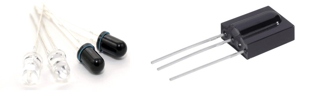
An IR LED is used to transmit data wirelessly in digital form (0 – LED OFF or 1 – LED ON).
An IR photodiode or IR phototransistor receives this data. The IR receiver (IR photodiode or IR phototransistor) gives different current values according to the intensity of light.
It is possible to modulate the data transmitted and there are special decoder IR receivers like TSOP1738 available that can receive the modulated data.
For more information about IR communication, refer to the topic IR Communication in the sensors and modules section.
Connection Diagram of IR LED, Photodiode with MSP-EXP430G2 TI Launchpad
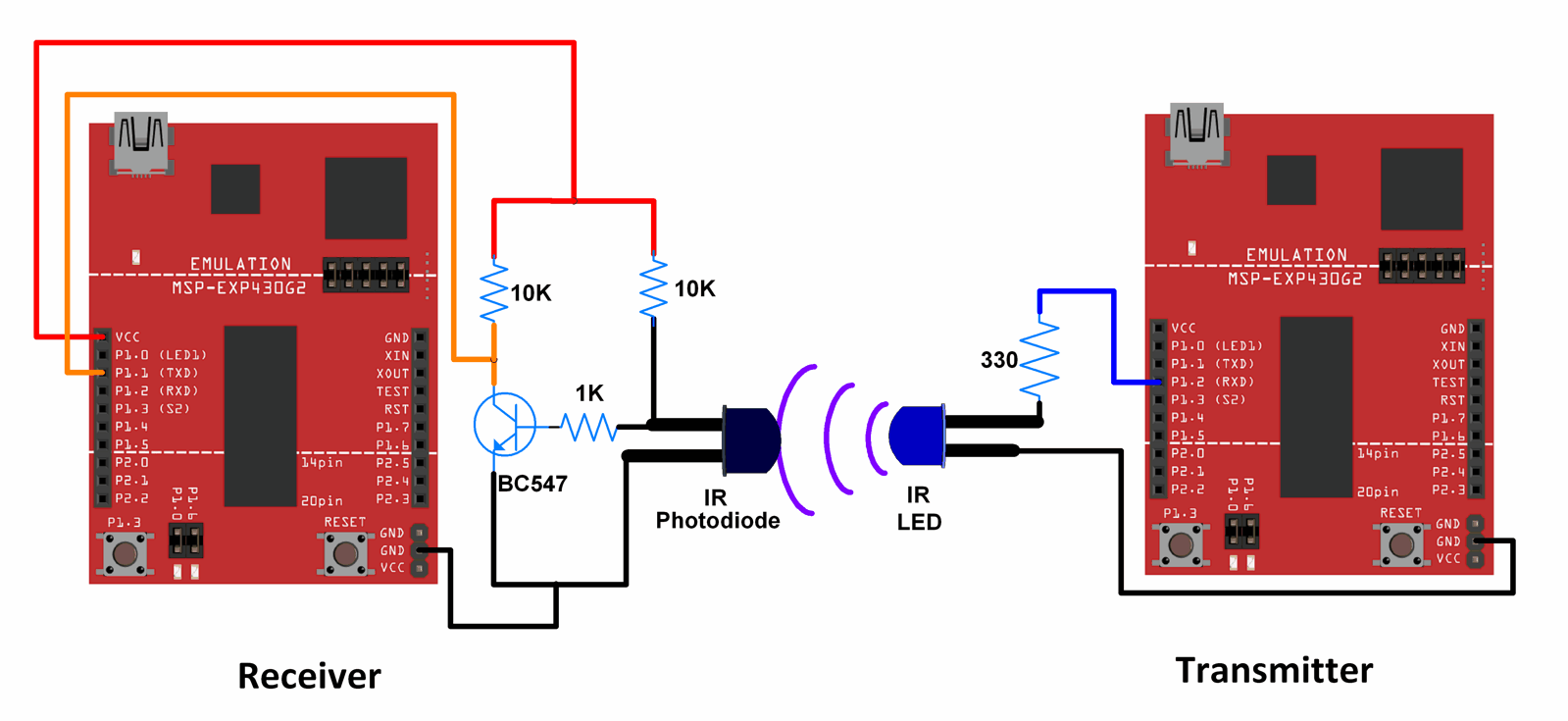
Note: For the TI Launchpad board, P1.1 is the Rx pin and P1.2 is the Tx pin when the jumpers are positioned for using Hardware Serial. Here, we are using, Hardware Serial, hence P1.1 is the Rx pin and P1.2 is the Tx pin.
When jumpers are positioned for software serial, P1.1 acts as the Tx pin, and P1.2 acts as the Rx pin.
Note: In the diagram shown above, for the IR LED as well as IR photodiode, the longer lead is the Anode and the shorter lead is the Cathode.
Also, the Photodiode is used in the reverse-biased mode (It is designed to operate in the reverse-biased mode).
Connection Diagram of IR LED, TSSOP1738 with MSP-EXP430G2 TI Launchpad
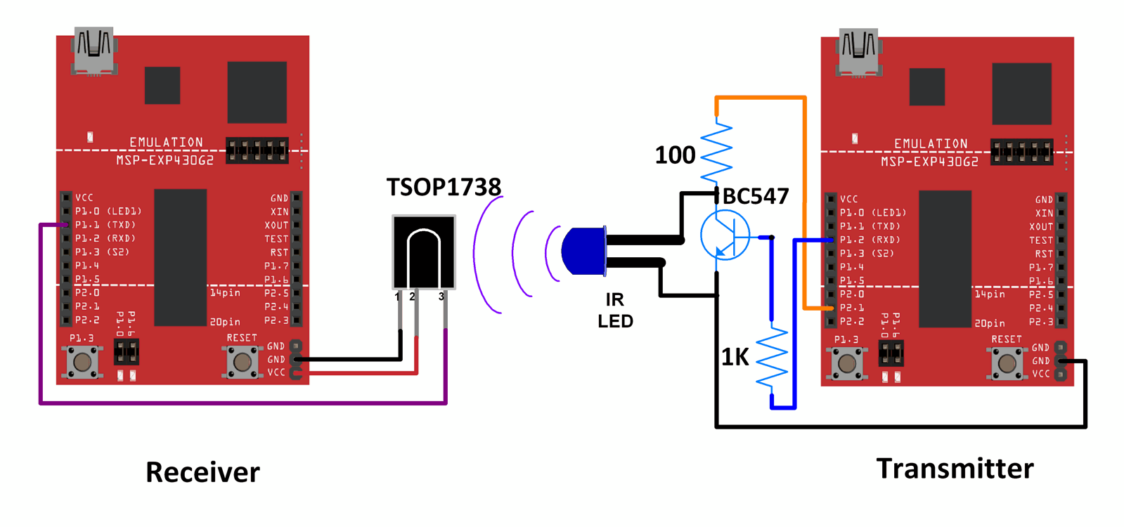
Note: For the TI Launchpad board, P1.1 is the Rx pin and P1.2 is the Tx pin when the jumpers are positioned for using Hardware Serial. Here, we are using, Hardware Serial, hence P1.1 is the Rx pin and P1.2 is the Tx pin.
When jumpers are positioned for software serial, P1.1 acts as the Tx pin and P1.2 acts as the Rx pin.
Note: In the diagram shown above, for the IR LED, the longer lead is the Anode and the shorter lead is the Cathode.
The data from the transmitter side is modulated at 38 kHz before transmission.
The TSOP1738 is an IR Receiver with the capability to demodulate signals that have been modulated at a frequency of 38 kHz.
Any other TSOP17xx receiver like the TSOP1730 can also be used instead of TSOP1738. The only difference is the carrier frequency that it can demodulate. For example, TSOP1730 can demodulate signals that have a carrier frequency of 30 kHz. Corresponding changes in the modulation scheme need to be made at the transmitter side if TSOP1730 or some other receiver is used.
Wireless IR communication between two MSP-EXP430G2 TI Launchpads.
Here, a simple count is transmitted from the transmitter using the IR LED. This count is received at the receiver by an IR photodiode or a TSOP1738. The count is transmitted as it is when the receiver is using IR photodiode. The count is modulated at 38 kHz when the receiver is using TSOP1738.
Note: IR is used just as a medium of data transmission between the transmitter and receiver. Data is being sent using the USART protocol.
Tread Carefully: MSP-EXP430G2 TI Launchpad board has a RAM of 512 bytes which is easily filled, especially while using different libraries. There are times when you need the Serial buffer to be large enough to contain the data you want and you will have to modify the buffer size for the Serial library. While doing such things, we must ensure that the code does not utilize more than 70% RAM. This could lead to the code working in an erratic manner, working well at times, and failing miserably at others.
There are times when the RAM usage may exceed 70% and the codes will work absolutely fine, and times when the code will not work even when the RAM usage is 65%.
In such cases, a bit of trial and error with the buffer size and/or variables may be necessary.
Code for IR Communication between IR LED and IR Photodiode Using TI Launchpad
Sketch for Transmitter
void setup() {
  Serial.begin(9600);	/* Define baud rate for serial communication */
  Serial.println("Transmitter");
}

void loop() {
  int count;
  for(count = 0; count<100; count++)
  {
    Serial.println(count);
    delay(1000);
  }
}
Sketch For Receiver
void setup() {
  Serial.begin(9600);	/* Define baud rate for serial communication */
  Serial.println("Receiver");
}

void loop() {
if(Serial.available())	/* If data is available on serial port */
  {
    Serial.print(char(Serial.read()));	/* Print character received on to the serial monitor */
  }
}
Video IR Communication using MSP-EXP430G2 TI Launchpad
Code for IR Communication between IR LED and TSOP1738 using TI Launchpad
Sketch For Transmitter
#define cr_pin 9

void setup() {
  Serial.begin(1200);	/* Define baud rate for serial communication */
  tone(cr_pin, 38000);	/* For modulation at 38kHz */
  Serial.println("Transmitter");
}

void loop() {
  int count;
  for(count = 0; count<100; count++)
  {
    Serial.println(count);
    delay(1000);
  }
}
Sketch For Receiver
void setup() {
  Serial.begin(1200);	/* Define baud rate for serial communication */
  Serial.println("Receiver");
}

void loop() {
if(Serial.available())	/* If data is available on serial port */
  {
    Serial.print(char(Serial.read()));	/* Print character received on to the serial monitor */
  }
}
Video of IR and TSSOP1738 Communication using MSP-EXP430G2 TI Launchpad
Components Used |
||
|---|---|---|
| TI Launchpad MSP-EXP430G2 TI Launchpad MSP-EXP430G2 |
X 1 | |
| IR LED Infrared Emitters IR LED Infrared Emitters |
X 1 | |
| TSOP1738 Infrared Receivers Infrared Receivers 38kHz IR Receiver |
X 1 | |
| Breadboard Breadboard |
X 1 | |
| Arduino UNO Arduino UNO |
X 1 | |
Downloads |
||
|---|---|---|
|
|
IR_Communication_With_TI_Launchpad_INO | Download |