Introduction
The Serial Peripheral Interface (SPI) is a bus interface connection protocol originally started by Motorola Corp. It uses four pins for communication.
SDI (Serial Data Input)
SDO (Serial Data Output)
SCLK (Serial Clock)
CS (Chip Select)
It has two pins for data transfer called as SDI (Serial Data Input) and SDO (Serial Data Output). SCLK (Serial Clock) pin is used to synchronize data transfer and Master provides this clock. CS (Chip Select) pin is used by master to select slave device.
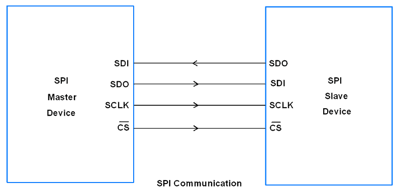
SPI devices have shift registers to send and receive data. Whenever master need to send data, it places data on shift register and generate required clock. Whenever master want to read data, slave places data on shift register and master generate required clock. Note that SPI is full duplex communication protocol i.e. data on master and slave shift registers get interchanged at a same time.
MBED SPI Communication
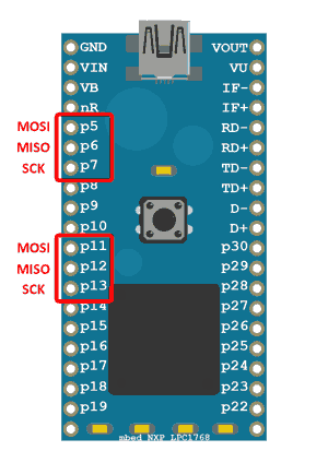
In the MBED board there are two SPIs are available.
The default settings of the SPI interface are 1MHz, 8-bit, Mode 0.
SPI Pins For ARM MBED
SPI Functions for MBED LPC1768
Now let’s see some basic functions related to SPI communication used in MBED.
SPI (PinName mosi, PinName miso, PinName sclk, PinName ssel=NC)
Create a SPI Object first connected to the specified SPI pins.
mosi: SPI Master Out, Slave In pin
miso: SPI Master In, Slave Out pin
sclk: SPI Clock pin
ssel: SPI chip select pin
e.g.
SPI spi(D11, D12, D13);
Following member functions are used created by user.
format (int bits, int mode)
Configure the data transmission format
bits: Number of bits per SPI frame (4 - 16)
mode: Clock polarity and phase mode (0 - 3)
e.g.
spi.format(8,3);| mode | POL | PHA |
| 0 | 0 | 0 |
| 1 | 0 | 1 |
| 2 | 1 | 0 |
| 3 | 1 | 1 |
frequency (int hz = 1000000)
To set the SPI clock frequency
Hz: SCLK frequency in hz (default = 1MHz)
e.g.
spi.frequency(1000000);
write (int value)
This function is used to write (send) data to the slave.
Value: send data to the slave SPI
e.g.
spi.write (0x89);
Example
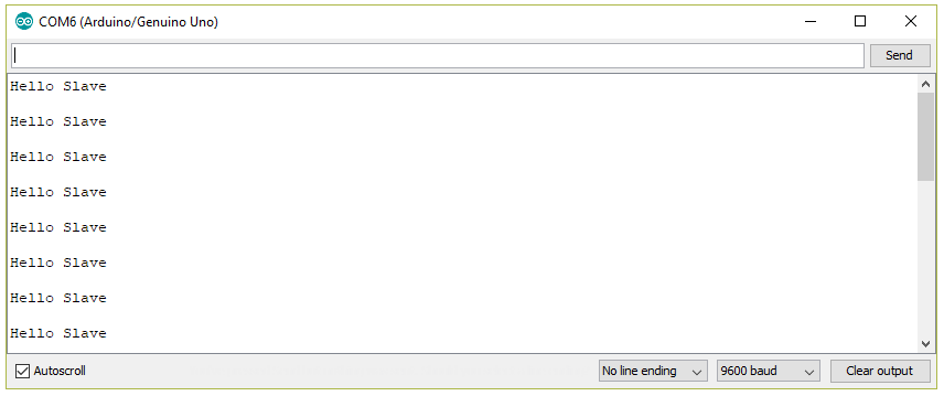
Here, we will transfer the "Hello Slave\n" string from MBED board to the Arduino board using SPI communication protocol.
To know about Arduino SPI functions you can refer link.
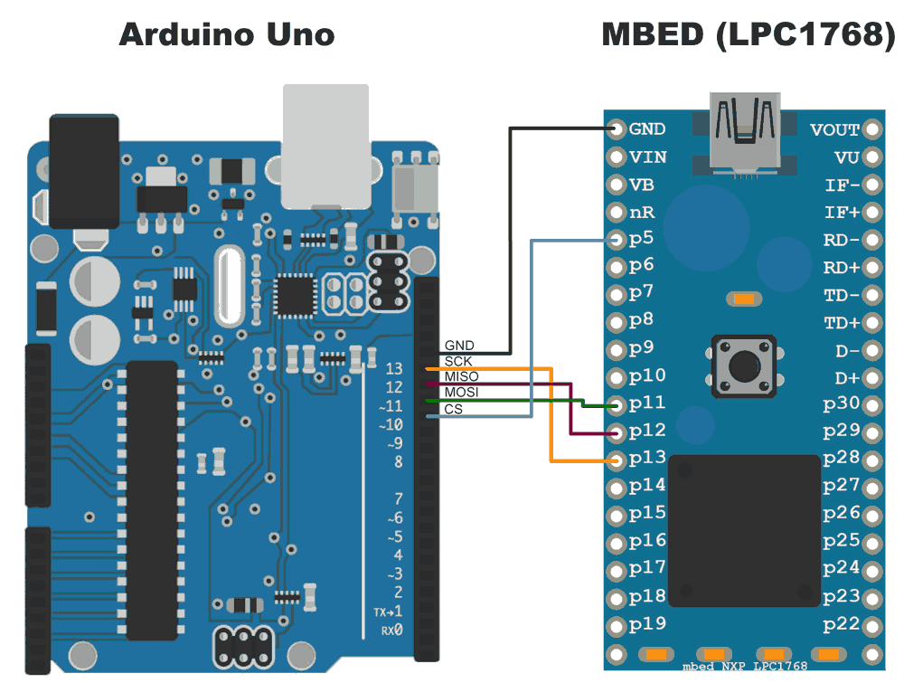
ARM MBED SPI Interfacing Diagram
Program
MBED Source code for SPI As a Master
#include "mbed.h"

SPI spi(p11, p12, p13); // mosi, miso, sclk
DigitalOut cs(p5);
const char buff[]="Hello Slave\n";

int main() {
	// Chip must be deselected
	cs = 1;
	// Setup the spi for 8 bit data, high steady state clock,
	// second edge capture, with a 1MHz clock rate
	spi.format(8,3);
	spi.frequency(1000000);

while(1) {
    // Select the device by seting chip select low
    cs = 0;
	for(int i=0; i<sizeof buff; i++)  /* transfer buff data per second */
	spi.write(buff[i]);
	cs = 1;
	wait(100);
	}
}
Arduino Sketch for SPI as a slave
#include <SPI.h>

char buff [100];
volatile byte index;
volatile bool receivedone;  /* use reception complete flag */

void setup (void)
{
  Serial.begin (9600);
  SPCR |= bit(SPE);         /* Enable SPI */
  pinMode(MISO, OUTPUT);    /* Make MISO pin as OUTPUT */
  index = 0;
  receivedone = false;
  SPI.attachInterrupt();    /* Attach SPI interrupt */
}

void loop (void)
{
  if (receivedone)          /* Check and print received buffer if any */
  {
    buff[index] = 0;
    Serial.println(buff);
    index = 0;
    receivedone = false;
  }
}

// SPI interrupt routine
ISR (SPI_STC_vect)
{
  uint8_t oldsrg = SREG;
  cli();
  char c = SPDR;
  if (index <sizeof buff)
  {
    buff [index++] = c;
    if (c == '\n'){     /* Check for newline character as end of msg */
     receivedone = true;
    }
  }
  SREG = oldsrg;
}
Output Window
Components Used |
||
|---|---|---|
| ARM mbed 1768 LPC1768 Board ARM mbed 1768 Board |
X 1 | |
| Arduino UNO Arduino UNO |
X 1 | |