Introduction
Pulse Width Modulation (PWM) is a technique by which width of a pulse is varied while keeping the frequency constant.
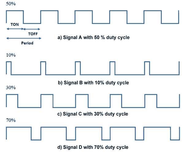
A period of a pulse consists of an ON cycle (HIGH) and an OFF cycle (LOW). The fraction for which the signal is ON over a period is known as duty cycle.
Duty Cycle (In %) = TON / (TON+TOFF) x 100
E.g. Consider a pulse with a period of 10ms which remains ON (high) for 2ms.The duty cycle of this pulse will be
D = (2ms / 10ms) x 100 = 20%
Through PWM technique, we can control the power delivered to the load by using ON-OFF signal.
Pulse Width Modulated signals with different duty cycle are shown below.
PWM Pins of ARM MBED Board
In the MBED board, there are total 6 PWM pins available from pin p21 to p26 as shown in below image.
.png)
PWM Functions for MBED
The basic functions for PWM of MBED LPC1768 are as follows.
PwmOut (pin)
Create a PWM Object first connected to the specified pin
pin: pin name where you want to generate PWM output (from i.e. p21 to p26).
e.g.
PwmOut led(LED1)
write()
Set the output duty-cycle in percentage (percentage in float).
e.g.
led.write(0.50f) // 50% duty cycle, relative to period
Note:
led.write()function is used to initialize duty cycle. But alternatively we can assign direct value to led object created by us.e.g.
e.g. led = led +0.1;
Example
Let’s write a program to generate PWM wave and change the brightness (fade) of led continuously.
ARM MBED PWM Program
// Fade a led on.
#include "mbed.h"   //include mbed file
PwmOut led(LED1);   //Define LED1 as a PWM Output Pin

int main() {
    while(1) {
        led = led + 0.01;	//shorthand for led.write()
        wait(0.2);		//wait for 200ms
        if(led == 1.0) {
        led = 0;		//turn off led1
        }
    }
}
Components Used |
||
|---|---|---|
| ARM mbed 1768 LPC1768 Board ARM mbed 1768 Board |
X 1 | |