Introduction
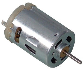
DC Motor
DC motor converts electrical energy in the form of Direct Current into mechanical energy.
In case of a motor, the mechanical energy produced is in the form of rotational movement of the motor shaft.
The direction of rotation of the shaft of the motor can be reversed by reversing the direction of Direct Current through the motor.
The motor can be rotated at a certain speed by applying a fixed voltage to it. If the voltage varies, the speed of the motor varies.
Thus, the DC motor speed can be controlled by applying varying DC voltage; whereas the direction of rotation of the motor can be changed by reversing the direction of current through it.
For applying varying voltage, we can make use of PWM technique.
For reversing the current, we can make use of H-Bridge circuit or motor driver ICs that employ the H-Bridge technique or any other mechanisms.
For more information about DC motors and how to use them, H-Bridge circuit configuration, PWM technique, refer the topic DC Motors in the sensors and modules section.
For information about PWM in LPC2148 and how to use it, refer the topic PWM in LPC2148 in the ARM7-LPC2148 inside section.
Here we will be using ADC feature of LPC2148.
For information about ADC in LPC2148 and how to use it, refer the topic ADC in LPC2148 in the ARM7-LPC2148 inside section.
Interfacing Diagram
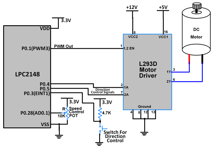 Interfacing DC Motor with LPC2148
Example
Here, we are going to control the speed and rotational direction of DC motor using LPC2148.
Here, a potentiometer is used as a means for speed control and an input from tactile switch is used to change the direction of the motor.
L293D motor driver IC is used for controlling the direction of the motor.
PWM wave generated on the LPC2148 is used to provide a variable voltage to the motor through the L293D.
Programming Steps
- Configure P0.3 as external interrupt pin (You may use some other external interrupt pin as well)
- Configure P0.1 as PWM pin (You may use some other PWM pin as well)
- Configure P0.28 as ADC pin (You may use some other ADC pin as well)
- Read the ADC input
- Generate a PWM wave corresponding to the value of the ADC input (Duty cycle of PWM wave directly proportional to ADC input)
- ISR for external interrupt pin is used for changing direction motor by toggling the control signals input to the motor driver IC.
Program
/*
  DC motor interfacing with LPC2148(ARM7)
  http://www.electronicwings.com/arm7/dc-motor-interfacing-with-lpc2148
*/

#include <lpc214x.h>
#include <stdint.h>
#include <stdbool.h>

volatile bool driver_ip1 = 1;
volatile bool driver_ip2 = 0;
volatile uint32_t result = 20;

void delay_ms(uint16_t j)
{
    uint16_t x,i;
	for(i=0;i<j;i++)
	{
    for(x=0; x<6000; x++);    /* loop to generate 1 milisecond delay with Cclk = 60MHz */
	}
}

__irq void PWM_ISR (void)
{
	if ( PWMIR & 0x0001 )
	{
		PWMIR = 0x0001;	/* Clear interrupt for PWM0 */
	}

	if ( PWMIR & 0x0008 )
	{
		PWMIR = 0x0008; /* Clear interrupt for PWM3 */
	}
	VICVectAddr = 0x00000000;
}

__irq void ADC0_ISR (void)
{
	result = AD0DR1;
	result = (result>>6);
	result = (result & 0x000003FF);
	VICVectAddr = 0x00000000;
}


__irq void EINT1_ISR (void)
{
	if( driver_ip1 == 1 )
	{
		driver_ip1 = 0;
	}
	else{
		driver_ip1 = 1;
	}
	if( driver_ip2 == 1 )
	{
		driver_ip2 = 0;
	}
	else{
		driver_ip2 = 1;
	}
	delay_ms(100);
	EXTINT = 0x02; /* Clear interrupt for EXT INT1 */
	VICVectAddr = 0x00000000;
}


int main (void)
{
	PINSEL0 = PINSEL0 | 0x000000C0; /* Configure P0.3 as EINT1 */
	PINSEL0 = PINSEL0 | 0x00000008; /* Configure P0.1 as PWM3 */
	PINSEL1 = 0x01000000; /* P0.28 as AD0.1 */
	EXTMODE = 0x02; /* Edge sensitive EINT1 */
	EXTPOLAR = 0x00; /* Falling sensitivity for EINT1 */
	EXTINT = 0x02; /* Clearing EINT1 flag	 */
	VICVectAddr0 = (unsigned) PWM_ISR; /* T0 ISR Address */
	VICVectCntl0 = (0x00000020 | 8); /* Enable PWM IRQ slot */
	VICIntEnable = VICIntEnable | 0x00000100; /* Enable PWM interrupt */
	VICIntSelect = VICIntSelect | 0x00000000; /* PWM configured as IRQ */
	VICVectAddr1 = (unsigned) ADC0_ISR; /* EINT1 ISR Address */
	VICVectCntl1 = (0x00000020 | 18); /* Enable EINT1 IRQ slot */
	VICIntEnable = VICIntEnable | 0x00040000; /* Enable EINT1 interrupt */
	VICIntSelect = VICIntSelect | 0x00000000; /* EINT1 configured as IRQ */
	VICVectAddr2 = (unsigned) EINT1_ISR; /* EINT1 ISR Address */
	VICVectCntl2 = (0x00000020 | 15); /* Enable EINT1 IRQ slot */
	VICIntEnable = VICIntEnable | 0x00008000; /* Enable EINT1 interrupt */
	VICIntSelect = VICIntSelect | 0x00000000; /* EINT1 configured as IRQ */
	float percent;
	AD0CR = 0x00200402; /* ADC operational, 10-bits, 11 clocks for conversion */
	AD0INTEN = 0x00000002; /* Enable AD0.1 interrupt */
	PWMTCR = 0x02; /* Reset and disable counter for PWM */
	PWMPR = 0x0E; /* Prescale Register value */
	PWMMR0 = 100000; /* Time period of PWM wave */
	PWMMR3 = 30000;	/* Ton of PWM wave */
	PWMMCR = 0x00000203;	/* Reset and interrupt on MR0 match, interrupt on MR3 match */
	PWMLER = 0x09;	/* Latch enable for PWM3 and PWM0 */
	PWMPCR = 0x0800;	/* Enable PWM3 and PWM 0, single edge controlled PWM */
	PWMTCR = 0x09;	/* Enable PWM and counter */
	IO0DIR = IO0DIR | 0x00000030;	/* P0.4 and P0.5 as motor driver i/p pins (output) */
	IO0PIN = ( ( IO0PIN | 0x00000010 ) & 0xFFFFFFDF ) ;
	while(1)
	{
			AD0CR = AD0CR | (1<<24); /* Start ADC Conversion */
			percent = (result/1023.0);
			PWMMR3 = (int)(percent * 100000);
			PWMLER = 0x08;
			if( (driver_ip1 == 1) && (driver_ip2 == 0) )
			{
					IO0PIN = ( ( IO0PIN | 0x00000010 ) & 0xFFFFFFDF ) ;
			}
			if( (driver_ip1 == 0) && (driver_ip2 == 1) )
			{
					IO0PIN = ( ( IO0PIN | 0x00000020 ) & 0xFFFFFFEF ) ;
			}
	}
}
Video
Components Used |
||
|---|---|---|
| ARM7 LPC2148 ARM7 LPC2148 |
X 1 | |
| L293D Driver L293D Driver |
X 1 | |
| Mini Push Button Switch - 5-6mm Mini Push Button Switch - 5-6mm |
X 1 | |
| Breadboard Breadboard |
X 1 | |
Downloads |
||
|---|---|---|
|
|
DC_Motor_uVision_Project | Download |