Introduction
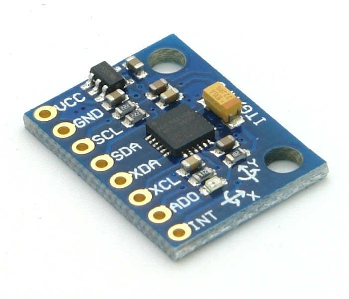 MPU6050 Module
MPU6050 sensor module is an integrated 6-axis Motion tracking device.
- It has a 3-axis Gyroscope, 3-axis Accelerometer, Digital Motion Processor and a Temperature sensor, all in a single IC.
- It can accept inputs from other sensors like 3-axis magnetometer, pressure sensor using its Auxiliary I2C bus.
- If external 3-axis magnetometer is connected, it can provide complete 9-axis Motion Fusion output.
- A microcontroller can communicate with this module using I2C communication protocol.
- Gyroscope and accelerometer reading along X, Y and Z axes are available in 2’s complement form. Temperature reading is available in signed integer form.
- Gyroscope readings are in degrees per second (dps) unit; Accelerometer readings are in g unit; and Temperature reading is in degrees Celsius.
For more information about MPU6050 Sensor Module and how to use it, refer the topic MPU6050 Sensor Module in the sensors and modules section.
Interfacing Diagram
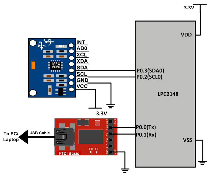 Interfacing MPU6050 Module with LPC2148
The MPU6050 communicates using I2C protocol. LPC2148 I2C0 interface is used for this purpose.
P0.2 and P0.3 are configured as SCL0 and SDA0 using the PINSEL register.
For information on I2C in LPC2148 and how to use it, refer the topic I2C in LPC2148 in the ARM7-LPC2148 inside section.
In this code, UART0 feature of LPC2148 has been used for displaying the accelerometer parameters. For information about UART0 in LPC2148 and how to use it, refer the topic UART in LPC2148 in the ARM7-LPC2148 inside section.
Example
A program to read the accelerometer, gyroscope and temperature parameters of MPU6050 and display it on PC terminal using UART0 of LPC2148.
Program
/*
  MPU6050 interfacing with LPC2148(ARM7)
  http://www.electronicwings.com/arm7/mpu6050-gyroscope-accelerometer-temperature-interfacing-with-lpc2148
*/

#include <lpc214x.h>
#include <stdint.h>
#include <stdio.h>
#define MPU_WRITE_ADDR 0xD0
#define MPU_READ_ADDR 0xD1

char receive_string[100];

void delay_ms(uint16_t j) /* Function for delay in milliseconds */
{
    uint16_t x,i;
	for(i=0;i<j;i++)
	{
    for(x=0; x<6000; x++);    /* loop to generate 1 millisecond delay with Cclk = 60MHz */
	}
}

void UART0_init(void)
{
	PINSEL0 = PINSEL0 | 0x00000005;	/* Enable UART0 Rx0 and Tx0 pins of UART0 */
	U0LCR = 0x83;	/* DLAB = 1, 1 stop bit, 8-bit character length */
	U0DLM = 0x00;	/* For baud rate of 9600 with Pclk = 15MHz */
	U0DLL = 0x61;	/* We get these values of U0DLL and U0DLM from formula */
	U0LCR = 0x03; /* DLAB = 0 */
}

void UART0_TxChar(char ch) /* A function to send a byte on UART0 */
{
	U0THR = ch;
	while( (U0LSR & 0x40) == 0 );	/* Wait till THRE bit becomes 1 which tells that transmission is completed */
}

void UART0_SendString(char* str) /* A function to send string on UART0 */
{
	uint8_t i = 0;
	while( str[i] != '\0' )
	{
		UART0_TxChar(str[i]);
		i++;
	}
}

void I2C_INIT(void)
{
	PINSEL0 = PINSEL0 | 0x00000050; /* P0.2 and P0.3 as SCL0 and SDA0 */
	I2C0CONSET = 0x40; /* I2C Enable */
	I2C0SCLL = 0x32; /* I2C bit frequency 300 kHz with 50% duty cycle */
	I2C0SCLH = 0x32;
}

void I2C_START(void)
{
	I2C0CONSET = 0x20; /* STA = 1 */
	while ( (I2C0CONSET & 0x08) == 0 ); /* Wait till SI = 1 */
	I2C0CONCLR = 0x28; /* Clear STA and SI */
}

void I2C_WRITE( char data )
{
	I2C0DAT = data;
	I2C0CONSET = 0x40; /* I2C Enable */
	while( (I2C0CONSET & 0x08) == 0 ); /* Wait till SI = 1 */
	I2C0CONCLR = 0x08; /* Clear SI */
}

unsigned char I2C_READ( void )
{
	I2C0CONSET = 0x44; /* I2C Enable with Acknowledge */
	while( (I2C0CONSET & 0x08) == 0 ); /* Wait till SI = 1 */
	I2C0CONCLR = 0x0C; /* Clear SI and Acknowledge */
	return I2C0DAT;
}

unsigned char I2C_READ1( void )
{
	I2C0CONSET = 0x40; /* I2C Enable */
	while( (I2C0CONSET & 0x08) == 0 ); /* Wait till SI = 1 */
	I2C0CONCLR = 0x08; /* Clear SI  */
	return I2C0DAT;
}

void I2C_MULTIREAD( char* arr , int bytes )
{
	uint8_t i = 0;
	while( ( bytes - 1 ) != 0 )
	{
		I2C0CONSET = 0x44; /* I2C Enable with Acknowledge */
		while( (I2C0CONSET & 0x08) == 0 ); /* Wait till SI = 1 */
		I2C0CONCLR = 0x0C; /* Clear SI and Acknowledge */
		*( arr + i ) = I2C0DAT ;
		bytes--;
		i++;
	}
	I2C0CONSET = 0x40; /* I2C Enable */
	while( (I2C0CONSET & 0x08) == 0 ); /* Wait till SI = 1 */
	I2C0CONCLR = 0x08; /* Clear SI */
	*( arr + i ) = I2C0DAT ;
}

void I2C_STOP( void )
{
	I2C0CONSET = 0x50; /* STO = 1 */
}

void I2C_MPU_CUSTOM ( char reg, char regval )
{
	I2C_START();
	I2C_WRITE(MPU_WRITE_ADDR);
	I2C_WRITE(reg);
	I2C_WRITE(regval);
	I2C_STOP();
}


void MPU_INIT( void )
{
	delay_ms(200);

	I2C_MPU_CUSTOM(0x6B, 0x02); /* PWR_MGMT_1 PLL with Y-axis gyroscope reference  */

	I2C_MPU_CUSTOM(0x19, 0x07); /* SMPLRT_DIV Reg Select, SMPLRT = 1K */

	I2C_MPU_CUSTOM(0x1A, 0x00); /* CONFIG Reg Select */

	I2C_MPU_CUSTOM(0x1B, 0x00); /* CONFIG Reg Select, Full scale range +/- 250 degree/C */

	I2C_MPU_CUSTOM(0x1C, 0x00); /* ACCEL Reg Select, Full scale range +/- 2g */

	I2C_MPU_CUSTOM(0x23, 0x00); /* FIFO disabled */

	I2C_MPU_CUSTOM(0x24, 0x00); /* I2C Master Control, I2C Freq 348KHz */

	I2C_MPU_CUSTOM(0x37, 0x00); /* Interrupt pin configuration */

	I2C_MPU_CUSTOM(0x38, 0x01); /* Interrupt Enable, Data Ready Enable */

	I2C_MPU_CUSTOM(0x67, 0x00); /* Master delay reg */

	I2C_MPU_CUSTOM(0x68, 0x00); /* Signal path reset */

	I2C_MPU_CUSTOM(0x6A, 0x00); /* User Control */

	I2C_MPU_CUSTOM(0x6C, 0x00); /* PWR_MGMT_2 */

	I2C_MPU_CUSTOM(0x74, 0x00); /* FIFO R/W */
}

int main(void)
{
	int16_t  GX,GY,GZ,AX,AY,AZ,T;
	double XA,XG,YA,YG,ZA,ZG,TF;
	char data[14];
	char result[100];
	UART0_init();
	I2C_INIT();
	MPU_INIT();
    while(1)
    {
			I2C_START();
			I2C_WRITE(MPU_WRITE_ADDR);
			I2C_WRITE(0x3B);
			I2C_START();
			I2C_WRITE(MPU_READ_ADDR);
			I2C_MULTIREAD(data, 14);
			I2C_STOP();
			AX = (((int16_t)(data[0]<<8)) | ((int16_t)data[1]));
			AY = (((int16_t)(data[2]<<8)) | ((int16_t)data[3]));
			AZ = (((int16_t)(data[4]<<8)) | ((int16_t)data[5]));
			XA = (double)AX/16384.0;
			YA = (double)AY/16384.0;
			ZA = (double)AZ/16384.0;
			T = (((int16_t)(data[6]<<8)) | ((int16_t)data[7]));
			TF = ( ((double)T/340.00) + 36.53 ) ;
			GX = (((int16_t)(data[8]<<8)) | ((int16_t)data[9]));
			GY = (((int16_t)(data[10]<<8)) | ((int16_t)data[11]));
			GZ = (((int16_t)(data[12]<<8)) | ((int16_t)data[13]));
			XG = (double)GX/131.0;
			YG = (double)GY/131.0;
			ZG = (double)GZ/131.0;
			sprintf(result,"Ax=%lfg Ay=%lfg Az=%lfg T=%lf%cC Gx=%lf%c/s Gy=%lf%c/s Gz=%lf%c/s",XA,YA,ZA,TF,0xB0,XG,0xB0,YG,0xB0,ZG,0xB0);
			UART0_SendString(result);
			UART0_SendString("\r\n");
			delay_ms(1000);
	 }
 }
Video
Components Used |
||
|---|---|---|
| ARM7 LPC2148 ARM7 LPC2148 |
X 1 | |
| MPU6050 Gyroscope and Accelerometer MPU6050 (Gyroscope + Accelerometer + Temperature) is a combination of 3-axis Gyroscope, 3-axis Accelerometer and Temperature sensor with on-chip Digital Motion Processor (DMP). It is used in mobile devices, motion enabled games, 3D mice, Gesture (motion command) technology etc |
X 1 | |
| CP2103 USB TO UART BRIDGE CP2103 is single chip USB to UART Bridge. It supports USB 2.0 protocol. |
X 1 | |
Downloads |
||
|---|---|---|
|
|
MPU6050_uVision_Project | Download |