Introduction
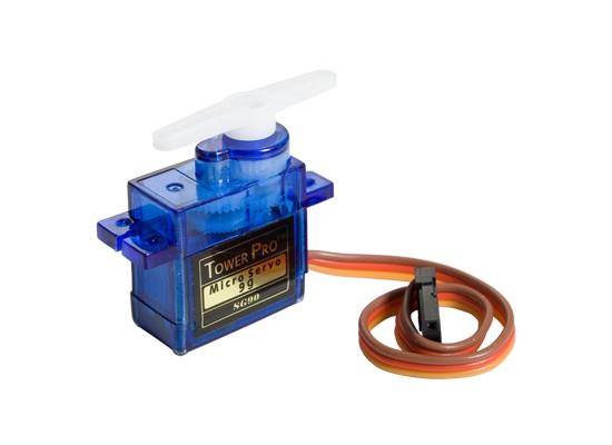
Servo Motor
A servo motor is an electric device used for precise control of angular rotation. It is used where precise control is required, like in case of control of robotic arm.
It consists of a suitable motor with control circuitry for precise position control of the motor shaft.
It is a closed loop system.
The rotation angle of the servo motor is controlled by applying a PWM signal to it.
By varying the width of the PWM signal, we can change the rotation angle and direction of the motor.
For more information about Servo Motor and how to use it, refer the topic Servo Motor in the sensors and modules section.
For information about PWM in LPC2148, refer the topic PWM in LPC2148 in the ARM7-LPC2148 inside section.
The SG90 servo requires a PWM with a time period of 20msec (50Hz wave).Basically, servo motor requires 50Hz wave with duty cycle variation in between 5-10% to rotate in -90° to +90 rotations.
But practically,
At ~0.65ms duty cycle we get shaft position at -90° of its rotation.
At ~1.6ms duty cycle we get shaft position at 0° (neutral) of its rotation.
At ~2.45ms duty cycle we get shaft position at +90° of its rotation.
The values may be different for the SG90 servo you are using. Vary the durations and find out the exact value for the three positions.
Generating PWM using LPC2148
To control servo motor position in between -90° to +90° of rotation, we need to generate PWM waveform of 50Hz with duty cycle variation from ~0.65ms to ~2.45ms. Any of the 6 PWMs of LPC2148 can be used for generating these waveforms.
Here, we will be using pin P0.1 configured as PWM3 (single edge controlled) for this purpose.
In LPC2148, PWM0 match register is used for the time period of the PWM wave to be generated, and one of the remaining 6 PWM match registers (PWM1-PWM6) can be used for the on time of the waveform. (PWM wave is generated on the corresponding PWM (PWM1-PWM6) pin).
Here we are using 12MHz oscillator. The configuration is such that, the CCLK (Processor clock) is 60MHz and the PCLK (Peripheral clock) is 30MHz. (This is done using the configuration wizard in the Startup.s file.)
We are using prescalar value of 30 for the PWM timer.
Hence the PWM timer will increment after every 1usec.
30Mhz/30 = 1MHz
1/1MHz = 1usec
The SG90 servo requires a PWM with a time period of 20msec (50Hz wave).
Hence, PWMMR0 (PWM match register 0)is loaded with 20000. (1usec x 20000 = 20msec).
On similar lines, PWMMR3 is loaded with different values based on the position of the servo required.
Interfacing Diagram
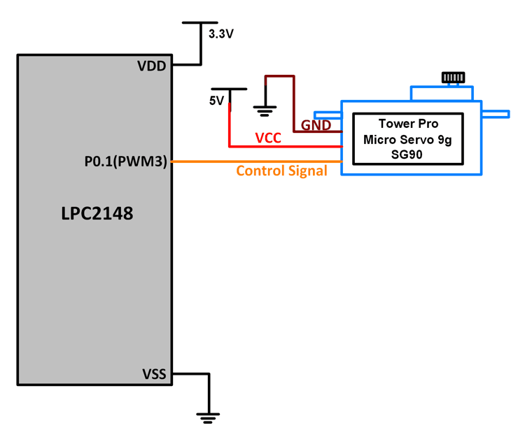 Interfacing Servo Motor With LPC2148
Example
Servo motor position control using PWM3 of LPC2148. The position is first changed from -90 to 0 to +90 degrees in 3 discrete steps, and then later, a continuous smooth sweep is made from -90 to +90 and back to -90 degrees position.
Single edge controlled PWM is used on pin P0.1. P0.1 is configured as PWM3 using the PINSEL register.
Program
/*
  Servo motor interfacing with LPC2148(ARM7)
  http://www.electronicwings.com/arm7/servo-motor-interfacing-with-lpc2148
*/

#include <lpc214x.h>
#include <stdint.h>

void delay_ms(uint16_t j)
{
    uint16_t x,i;
	for(i=0;i<j;i++)
	{
    for(x=0; x<6000; x++);    /* loop to generate 1 milisecond delay with Cclk = 60MHz */
	}
}

__irq void PWM_ISR (void)
{
	if ( PWMIR & 0x0001 )
	{
		PWMIR = 0x0001;
	}

	if ( PWMIR & 0x0008 )
	{
		PWMIR = 0x0008;
	}

	VICVectAddr = 0x00000000;
}

int main (void)
{
	//int16_t value = 1000;
	PINSEL0 = PINSEL0 | 0x00000008; /* Configure P0.1 as PWM3 */
	VICVectAddr0 = (unsigned) PWM_ISR; /* PWM ISR Address */
	VICVectCntl0 = (0x00000020 | 8); /* Enable PWM IRQ slot */
	VICIntEnable = VICIntEnable | 0x00000100; /* Enable PWM interrupt */
	VICIntSelect = VICIntSelect | 0x00000000; /* PWM configured as IRQ */
	PWMTCR = 0x02; /* Reset and disable counter for PWM */
	PWMPR = 0x1D; /* Prescale Register value */
	PWMMR0 = 20000; /* Time period of PWM wave, 20msec */
	PWMMR3 = 650;	/* Ton of PWM wave 0.65 msec */
	PWMMCR = 0x00000203;	/* Reset and interrupt on MR0 match, interrupt on MR3 match */
	PWMLER = 0x09;	/* Latch enable for PWM3 and PWM0 */
	PWMPCR = 0x0800;	/* Enable PWM3 and PWM 0, single edge controlled PWM */
	PWMTCR = 0x09;	/* Enable PWM and counter */
	while(1)
	{
		PWMMR3 = 650;	/* For -90 degree position */
		PWMLER = 0x08;
		delay_ms(2000);
		PWMMR3 = 1600;	/* For 0 degree rotation */
		PWMLER = 0x08;
		delay_ms(2000);
		PWMMR3 = 2450;	/* For +90 degree rotation */
		PWMLER = 0x08;
		delay_ms(2000);
		for(int16_t value = 650; value<2450; value++)
		{
			PWMMR3 = value;
			PWMLER = 0x08;
			delay_ms(5);
		}
		for(int16_t value = 2450; value>650; value--)
		{
			PWMMR3 = value;
			PWMLER = 0x08;
			delay_ms(5);
		}
	}
}
Video
Components Used |
||
|---|---|---|
| ARM7 LPC2148 ARM7 LPC2148 |
X 1 | |
| Servo Motor MG995 Servo Motor MG995 |
X 1 | |
Downloads |
||
|---|---|---|
|
|
Servo_Motor_uVision_Project | Download |