Introduction to Watchdog
- Watchdog Timer (WDT) can be helpful to automatically reset the system whenever a timeout occurs.
- System reset is required for preventing failure of the system in a situation of a hardware fault or program error.
- There are countless applications where the system cannot afford to get stuck at a point (not even for a small duration of time). For example, in a radar system, if the system hangs for 5 minutes, it can result in serious repercussions (an enemy plane or missile may go undetected resulting in huge losses).
- The system should be robust enough to automatically detect the failures quickly and reset itself in order to recover from the failures and function normally without errors.
- One can manually reset the system to recover from errors. But it is not always feasible to manually reset the system, especially once it has been deployed.
- To overcome such problems, a watchdog timer is necessary to automatically reset the system without human intervention.
LPC2148 has an inbuilt watchdog timer. The watchdog when enabled generates a system reset if the user program fails to feed (or reload) the watchdog within a predetermined amount of time.
- The watchdog consists of a fixed divide by 4 prescalar and a 32-bit counter. The clock is fed to the timer through the prescalar.
- The counter can be loaded with any value between 0xFF and 0xFFFFFFFF. If the counter is loaded with any value less than 0xFF, the counter is initialized with a value 0xFF.
- The watchdog needs to be fed with a pre-determined sequence of 0xAA followed by 0x55 before watchdog timer underflows to prevent reset/interrupt.
How does the Watchdog work?
Consider a pet dog. If you feed the dog at regular intervals, it will be happy. What happens if you do not feed it? Well, it will start barking and might even bite you.
Similarly, if you do not feed the watchdog at regular intervals before its timeout, it will cause a system reset.
Let’s see the registers that are used to control and start the Watchdog timer in LPC2148.
Watchdog Registers
1. WDMOD (Watchdog Mode Register)
- It is an 8-bit read-write register.
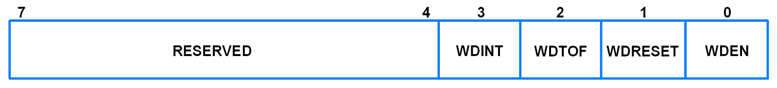
- It is used to control the operation of the watchdog.
- Bit 0 – WDEN (Watchdog Interrupt Enable)
- Bit 1 – WDRESET (Watchdog Reset Enable)
- Bit 2 – WDTOF (Watchdog Time-Out Flag)
This bit is set when the watchdog times out.It is cleared by software. - Bit 3 – WDINT (Watchdog Interrupt Flag)
This bit is set when the watchdog times out. This bit is cleared when any reset occurs.It is a read only bit.
| WDEN | WDRESET | Mode of Operation |
| 0 | 0 or 1 | Debug/Operate without watchdog running |
| 1 | 0 | Watchdog Interrupt Mode: Debug with watchdog interrupt but no WDRESET enabled. A watchdog counter underflow will set the WDINT flag and the watchdog interrupt request will be generated. |
| 1 | 1 | Watchdog Reset Mode: Operate with the watchdog interrupt and WDRESET enabled. A watchdog counter underflow will reset the microcontroller. Although the watchdog interrupt is also enabled (WDEN=1), it will not be recognized since the watchdog reset will clear the WDINT flag. |
2. WDTC (Watchdog Timer Constant Register)
- It is a 32-bit read-write register.

- Every time a sequence feed occurs, the WDTC content is loaded into the watchdog timer.
- The 8 least significant bits (bits 7:0) of this register are set to 1 on reset.
- Any value below 0xFF will cause 0xFF to be loaded in this register. Hence, the minimum timeout interval is (TPCLK * 256 * 4).
3. WDFEED (Watchdog Feed Register)
- It is an 8-bit write only register.

- Writing a 0xAA followed by 0x55 to this register will reload the watchdog timer with the WDTC value.
- This operation will also start the watchdog if it is enabled via the WDMOD register.
- Making WDEN bit 1 in the WDMOD register is not sufficient to start the watchdog. A valid feed sequence must be completed so that the watchdog is able to generate an interrupt/reset. Until then, the watchdog will ignore feed errors.
- Once a 0xAA is written to the FEED register, the next operation should be a 0x55 write to the FEED register, otherwise, the watchdog is triggered.
- The interrupt/reset will be generated during the second PCLK following an incorrect access to a watchdog timer register during a feed sequence.
- Interrupts should be disabled during the feed sequence. An abort condition will occur if an interrupt occurs during the feed sequence.
4. WDTV (Watchdog Timer Value Register)
- It is a 32-bit read only register.

- It is used to read the current value of watchdog timer.
How to use the Watchdog in LPC2148?
To use the watchdog timer, we need to follow the steps given below:
- Set the watchdog timer constant reload value in the WDTC register
- Select the mode using the WDMOD register
- Start the watchdog by feeding it with 0xAA followed by 0x55 in the WDFEED register
- Make sure to feed the watchdog again before the timer counter underflows in order to prevent reset/interrupt
- The Watchdog Time-Out Flag (WDTOF) can be monitored to determine if the watchdog has caused reset condition. The WDTOF flag must be cleared using software.
Example
Let’s write a simple code where watchdog timer will reset the system due to time out.
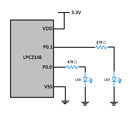
Here we have connected 2 LEDs to P0.0 and P0.1 of the LPC2148.
We will write a code for blinking LED on P0.0 with increasing amounts of delay.
The watchdog timer counter is loaded with 0x00007FFFF (524287) which gives a max duration of 139msec before the timer counter underflows and resets the system.
If the system is reset by the watchdog, it is indicated by turning on LED on P0.1.
TPCLK = 66.67nsec (PCLK = 15MHz)
Hence, (66.67nsec* 524287 * 4) = 139msec
Program for LPC2148 Watchdog timer
/*
  Watchdog in LPC2148(ARM7)
  http://www.electronicwings.com/arm7/lpc2148-watchdog-timer
*/

#include <lpc214x.h>
#include <stdint.h>

void delay_ms(uint16_t j)
{
    uint16_t x,i;
	for(i=0;i<j;i++)
	{
    for(x=0; x<6000; x++);    /* loop to generate 1 milisecond delay with Pclk=15MHz */
	}
}

int main(void)
{
	IO0DIR = IO0DIR | 0x00000003; /* P0.0,P0.1 as outputs for LEDs */
	IO0CLR = 0x00000003; /* LEDs OFF */
	delay_ms(3000);
	if ( WDMOD & 0x04 )
	{
		IO0CLR = 0x00000003;
		IO0SET = 0x00000002;	/* P0.1 LED ON */
		delay_ms(3000);  /* Indicate Watchdog Reset using LED at P0.1 */
		IO0CLR = 0x00000002; /* P0.1 LED OFF */
		delay_ms(2000);
	}
	WDTC = 0x0007FFFF; // For 139msec delay
	WDMOD = 0x03;// Watchdog interrupt enable with watchdog reset
	WDFEED = 0xAA;
	WDFEED = 0x55;
	IO0SET = 0x00000001;	/* P0.0 LED ON */
	delay_ms(50);
	IO0CLR = 0x00000001;	/* P0.0 LED OFF */
	delay_ms(50);
	WDFEED = 0xAA;
	WDFEED = 0x55;
	IO0SET = 0x00000001;
	delay_ms(55);
	IO0CLR = 0x00000001;
	delay_ms(55);
	WDFEED = 0xAA;
	WDFEED = 0x55;
	IO0SET = 0x00000001;
	delay_ms(60);
	IO0CLR = 0x00000001;
	delay_ms(60);
	WDFEED = 0xAA;
	WDFEED = 0x55;
	IO0SET = 0x00000001;
	delay_ms(65);
	IO0CLR = 0x00000001;
	delay_ms(65);
	WDFEED = 0xAA;
	WDFEED = 0x55;
	IO0SET = 0x00000001;
	delay_ms(70);
	IO0CLR = 0x00000001;
	delay_ms(70);
	WDFEED = 0xAA;
	WDFEED = 0x55;
	return 0;
}
Video
Components Used |
||
|---|---|---|
| ARM7 LPC2148 ARM7 LPC2148 |
X 1 | |
| LED 5mm LED 5mm |
X 1 | |
| Breadboard Breadboard |
X 1 | |