Introduction
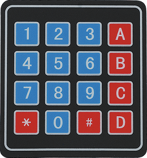
4x4 Keypad
Keypad is used as an input device to read the key pressed by the user and to process it.
4x4 keypad consists of 4 rows and 4 columns. Switches are placed between the rows and columns. A key press establishes a connection between corresponding row and column between which the switch is placed.
In order to read the key press, we need to configure the rows as outputs and columns as inputs.
Columns are read after applying signals to the rows in order to determine whether or not a key is pressed and if pressed, which key is pressed.
For more information about keypad and how to use it, refer the topic 4x4 Keypad in the sensors and modules section.
Interfacing Diagram
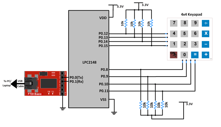 Interfacing 4x4 Keypad with LPC2148
Rows of the keypad R3-R0 are connected to pins P0.15-P0.12 respectively.
Columns of the keypad C3-C0 are connected to pins P0.11-P0.8 respectively.
Example
A program for reading the key pressed from a keypad and to display the key pressed on PC terminal using UART communication.
In this code, UART0 feature of LPC2148 has been used for displaying information regarding the key press. For information about UART0 in LPC2148 and how to use it, refer the topic UART in LPC2148 in the ARM7-LPC2148 inside section.
Program
/*
  Keypad interfacing with LPC2148(ARM7)
  http://www.electronicwings.com/arm7/4x4-keypad-interfacing-with-lpc2148
*/

#include <lpc214x.h>
#include <stdint.h>

char keypad[4][4] = {{'1', '2', '3', '+'},
                     {'4', '5', '6', '-'},
                     {'7', '8', '9', '*'},
                     {'.', '0', '=', '/'}};


void delay_ms(uint16_t j)
{
    uint16_t x,i;
	for(i=0;i<j;i++)
	{
    for(x=0; x<6000; x++);    /* loop to generate 1 milisecond delay with Cclk = 60MHz */
	}
}
void delay_us(uint16_t j)
{
    uint16_t x,i;
	for(i=0;i<j;i++)
	{
    for(x=0; x<6; x++);    /* loop to generate 1 milisecond delay with Cclk = 60MHz */
	}
}

void UART0_init(void)
{
	PINSEL0 = PINSEL0 | 0x00000005;	/* Enable UART0 Rx0 and Tx0 pins of UART0 */
	U0LCR = 0x83;	/* DLAB = 1, 1 stop bit, 8-bit character length */
	U0DLM = 0x00;	/* For baud rate of 9600 with Pclk = 15MHz */
	U0DLL = 0x61;	/* We get these values of U0DLL and U0DLM from formula */
	U0LCR = 0x03; /* DLAB = 0 */
}

void UART0_TxChar(char ch) /* A function to send a byte on UART0 */
{
	U0THR = ch;
	while( (U0LSR & 0x40) == 0 );	/* Wait till THRE bit becomes 1 which tells that transmission is completed */
}

void UART0_SendString(char* str) /* A function to send string on UART0 */
{
	uint8_t i = 0;
	while( str[i] != '\0' )
	{
		UART0_TxChar(str[i]);
		i++;
	}
}

unsigned char UART0_RxChar(void) /* A function to receive a byte on UART0 */
{
	while( (U0LSR & 0x01) == 0);	/* Wait till RDR bit becomes 1 which tells that receiver contains valid data */
		return U0RBR;
}


int main (void)
{
	/* P0.15-P0.12-->Rows(R3-R0)  P0.11-P0.8-->Columns(C3-C0)  */
	UART0_init();
	IO0DIR = 0x0000F000;
	delay_ms(5);
	int32_t col,row;
    while(1)
    {
		IO0PIN = (IO0PIN & 0xFFFF00FF) | 0x00000F00;
		delay_ms(5);
		while ((IO0PIN & 0x0000FF00) == 0x00000F00 )
		{

		}

		if( (IO0PIN & 0x00000F00) != 0x00000F00 )
		{
			delay_ms(50);
			if( (IO0PIN & 0x00000F00) != 0x00000F00 )
			{
				delay_ms(30);
				col = IO0PIN & 0x00000F00;

				while (1)
				{
					IO0PIN = (IO0PIN & 0xFFFF00FF) | 0x0000EF00;
					delay_ms(5);
					col = IO0PIN & 0x00000F00;
					delay_ms(1);

					if ((IO0PIN & 0x00000F00) != 0x00000F00 )
					{
						row = 0;
						break;
					}

					IO0PIN = (IO0PIN & 0xFFFF00FF) | 0x0000DF00;
					delay_ms(5);
					col = IO0PIN & 0x00000F00;
					delay_ms(1);
					if ( (IO0PIN & 0x00000F00) != 0x00000F00 )
					{
						row = 1;
						break;
					}

					IO0PIN = (IO0PIN & 0xFFFF00FF) | 0x0000BF00;
					delay_ms(5);
					col = IO0PIN & 0x00000F00;
					delay_ms(1);
					if ( (IO0PIN & 0x00000F00) != 0x00000F00 )
					{
						row = 2;
						break;
					}

					IO0PIN = (IO0PIN & 0xFFFF00FF) | 0x00007F00;
					delay_ms(5);
					col = IO0PIN & 0x00000F00;
					delay_ms(1);
					if ( (IO0PIN & 0x00000F00) != 0x00000F00 )
					{
						row = 3;
						break;
					}
					break;
				}
				char key;
				if ( col == 0x00000E00)
				{
					key = keypad[row][0];
				}

				else if ( col == 0x00000D00)
				{
					key = keypad[row][1];
				}

				else if ( col == 0x00000B00)
				{
					key = keypad[row][2];
				}

				else if ( col == 0x00000700)
				{
					key = keypad[row][3];
				}

				else continue;
				UART0_SendString("Key pressed : ");
				UART0_TxChar(key);
				UART0_SendString("\r\n");
			}
       }
   }
}
Video
Components Used |
||
|---|---|---|
| ARM7 LPC2148 ARM7 LPC2148 |
X 1 | |
| 4x4 Keypad Module Keypad is an input device which is generally used in applications such as calculator, ATM machines, computer etc. |
X 1 | |
| CP2103 USB TO UART BRIDGE CP2103 is single chip USB to UART Bridge. It supports USB 2.0 protocol. |
X 1 | |
| Breadboard Breadboard |
X 1 | |
Downloads |
||
|---|---|---|
|
|
Keypad_uVision_Project | Download |