Introduction
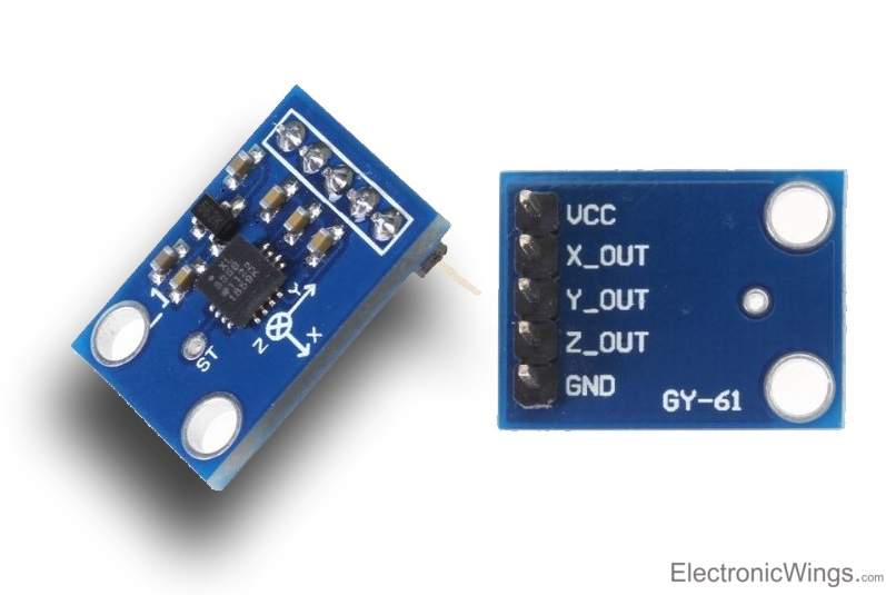 ADXL335 Accelerometer
Accelerometer is an electromechanical device that measures the force of acceleration due to gravity in g unit.
It can be used for tilt sensing applications (Example: In mobile phones, gaming applications etc).
The ADXL335 measures acceleration along X, Y and Z axes.
It gives analog voltage output proportional to the acceleration along the 3 axes.
These voltages can be converted to digital signal using ADC and then processed by microcontroller to find out the tilt.
For more information about ADXL335 accelerometer and how to use it, refer the topic ADXL335 Accelerometer Module in the sensors and modules section.
For information about ADC in LPC2148 and how to use it, refer the topic ADC in LPC2148 in the ARM7-LPC2148 inside section.
Interfacing Diagram
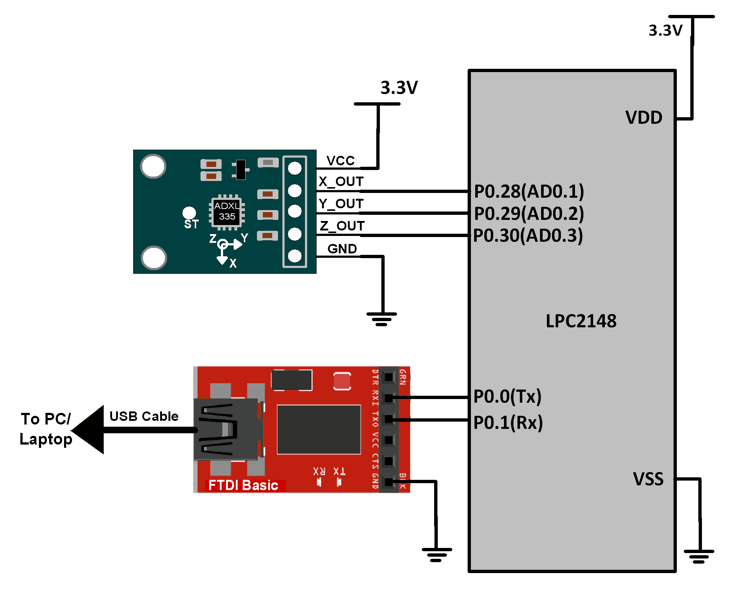 Interfacing ADXL335 Accelerometer Module with LPC2148
Analog voltages proportional to the acceleration along X, Y, and Z axes are available on the X_OUT, Y_OUT and Z_OUT pins respectively.
These voltages are given to ADC pins of LPC2148.
P0.28 (AD0.1), P0.29 (AD0.2) and P0.30 (AD0.3) are fed with X_OUT, Y_OUT, and Z_OUT signals respectively.
We are using UART0 feature of LPC2148 for displaying the accelerometer parameters on the serial terminal of PC. For information about UART0 in LPC2148 and how to use it, refer the topic UART in LPC2148 in the ARM7-LPC2148 inside section.
Example
Let’s program LPC2148 to find the acceleration along the X, Y and Z axes and display it on PC terminal using LPC2148 UART0.
Programming Steps
- Initialize UART0
- Configure any 3 ADC pins of choice (Here we have configured P0.28, 29, 30 as AD0.1, AD0.2, AD0.3)
- Read X, Y and Z data from the corresponding ADC pins
- Display data on a serial monitor after signal conditioning
Program
/*
  ADXL335 accelerometer interfacing with LPC2148(ARM7)
  http://www.electronicwings.com/arm7/adxl335-accelerometer-interfacing-with-lpc2148
*/

#include <lpc214x.h>
#include <stdint.h>
#include <stdio.h>

void delay_ms(uint16_t j)
{
    uint16_t x,i;
	for(i=0;i<j;i++)
	{
    for(x=0; x<6000; x++);    /* loop to generate 1 milisecond delay with Cclk = 60MHz */
	}
}

void UART0_init(void)
{
	PINSEL0 = PINSEL0 | 0x00000005;	/* Enable UART0 Rx0 and Tx0 pins of UART0 */
	U0LCR = 0x83;	/* DLAB = 1, 1 stop bit, 8-bit character length */
	U0DLM = 0x00;	/* For baud rate of 9600 with Pclk = 15MHz */
	U0DLL = 0x61;	/* We get these values of U0DLL and U0DLM from formula */
	U0LCR = 0x03; /* DLAB = 0 */
}

void UART0_TxChar(char ch) /* A function to send a byte on UART0 */
{
	U0THR = ch;
	while( (U0LSR & 0x40) == 0 );	/* Wait till THRE bit becomes 1 which tells that transmission is completed */
}

void UART0_SendString(char* str) /* A function to send string on UART0 */
{
	uint8_t i = 0;
	while( str[i] != '\0' )
	{
		UART0_TxChar(str[i]);
		i++;
	}
}

uint32_t ADC_READ1(void)
{
	uint32_t x_out;
	PINSEL1 = (PINSEL1 | 0x01000000); /* P0.28 as AD0.1 */
	AD0CR = 0x00200402; /* ADC1 operational, 10-bits, 11 clocks for conversion */
	AD0CR = AD0CR | (1<<24); /* Start Conversion */
	while ( !(AD0DR1 & 0x80000000) );
	x_out = AD0DR1;
	x_out = (x_out>>6);
	x_out = (x_out & 0x000003FF);
	return x_out;
}

uint32_t ADC_READ2(void)
{
	uint32_t y_out;
	PINSEL1 = (PINSEL1 | 0x04000000); /* P0.29 as AD0.2 */
	AD0CR = 0x00200404; /* ADC2 operational, 10-bits, 11 clocks for conversion */
	AD0CR = AD0CR | (1<<24); /* Start Conversion */
	while ( !(AD0DR2 & 0x80000000) );
	y_out = AD0DR2;
	y_out = (y_out>>6);
	y_out = (y_out & 0x000003FF);
	return y_out;
}

uint32_t ADC_READ3(void)
{
	uint32_t z_out;
	PINSEL1 = (PINSEL1 | 0x10000000); /* P0.30 as AD0.3 */
	AD0CR = 0x00200408; /* ADC3 operational, 10-bits, 11 clocks for conversion */
	AD0CR = AD0CR | (1<<24); /* Start Conversion */
	while ( !(AD0DR3 & 0x80000000) );
	z_out = AD0DR3;
	z_out = (z_out>>6);
	z_out = (z_out & 0x000003FF);
	return z_out;
}

int main(void)
{
	char result[70];
	uint32_t x_out1, y_out1, z_out1;
	double x_val, y_val, z_val;
	UART0_init();
	while(1)
	{
		x_out1 = ADC_READ1();
		delay_ms(10);
		y_out1 = ADC_READ2();
		delay_ms(10);
		z_out1 = ADC_READ3();
		delay_ms(10);
		x_val = ( ( ( (x_out1 * 3.3) / 1024 ) - 1.6 ) / 0.33 );
		y_val = ( ( ( (y_out1 * 3.3) / 1024 ) - 1.6 ) / 0.33 );
		z_val = ( ( ( (z_out1 * 3.3) / 1024 ) - 1.6 ) / 0.33 );
		sprintf(result,"x=%lfg, y=%lfg, z=%lfg",x_val,y_val,z_val);
		UART0_SendString(result);
		UART0_SendString("\r\n");
		delay_ms(1000);
	}
}
Video
Components Used |
||
|---|---|---|
| ARM7 LPC2148 ARM7 LPC2148 |
X 1 | |
| ADXL337 3-Axis Accelerometer ADXL337 is a low-power 3-axis accelerometer with signal conditioned outputs. |
X 1 | |
| CP2103 USB TO UART BRIDGE CP2103 is single chip USB to UART Bridge. It supports USB 2.0 protocol. |
X 1 | |
Downloads |
||
|---|---|---|
|
|
Accelerometer_uVision_Project | Download |