Overview of nRF24L01
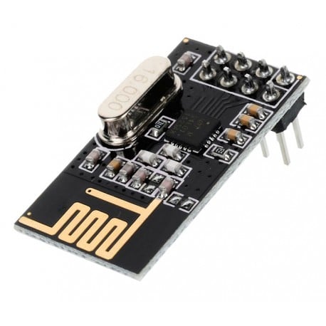
NRF24L01 is a wireless transceiver module which operates in the 2.4GHz ISM frequency band.
It is used to communicate data wirelessly which is specially designed for ultra-low power applications.
It can be configured and operated through SPI Protocol.
It can transmit data at a rate up to 2 Mbps.
This module can use 125 different channels which makes possible to have network of 125 independently working modems in one place.
Each channel has up to 6 addresses that means it can communicate with 6 other devices simultaneously.
The communication range is up to 100 meters and it specially designed for ultra-low power applications.
It operates on 1.9V to 3.6V power supply range, it takes 12mA of current during transmission mode which is even less than a single LED.
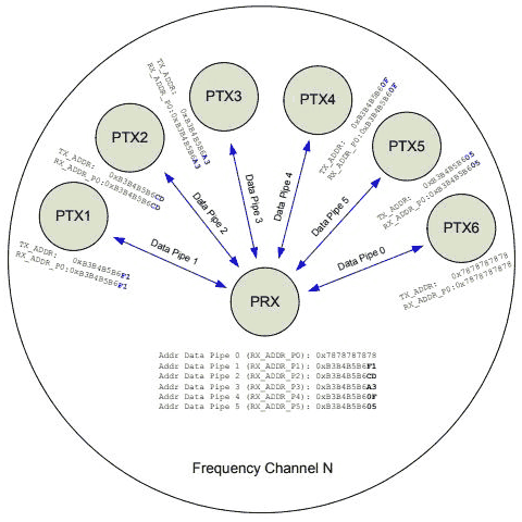
The multi-receiver capacity of nRF24L01 is having up to 6 channels (pipes) of radio communication open in a receiving or read mode simultaneously. This takes the form of a hub receiver (PRX - primary receiver) and up to six transmitter nodes (PTX1 - PTX6 primary transmitters). In the above diagram, six reading (Data) pipes are opened in the primary receiver hub (PRX). Each PTX node links to one of these pipes to use both in transmitting and receiving (TX toward the hub being the primary direction of data flow, but the PTX nodes are RX capable as well).
Note: that the hub can also stop listening and act as a transmitter, transmitting (or writing) to the PTX nodes but this can only be done one pipe or node at a time.
The addresses or pipes must have a distinct pattern of bytes, only the fifth byte is entirely unique among all the pipes and is known as the Least Significant Byte (LSB). Pipe 0 is assigned all five bytes independently. Pipe 1 is also assigned all five bytes independently, but then the first four bytes (MSBs) of pipe 1 also become the first four bytes of pipes 2 - 5 if they exist.
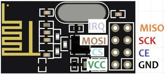
Pin Diagram of nRF24L01
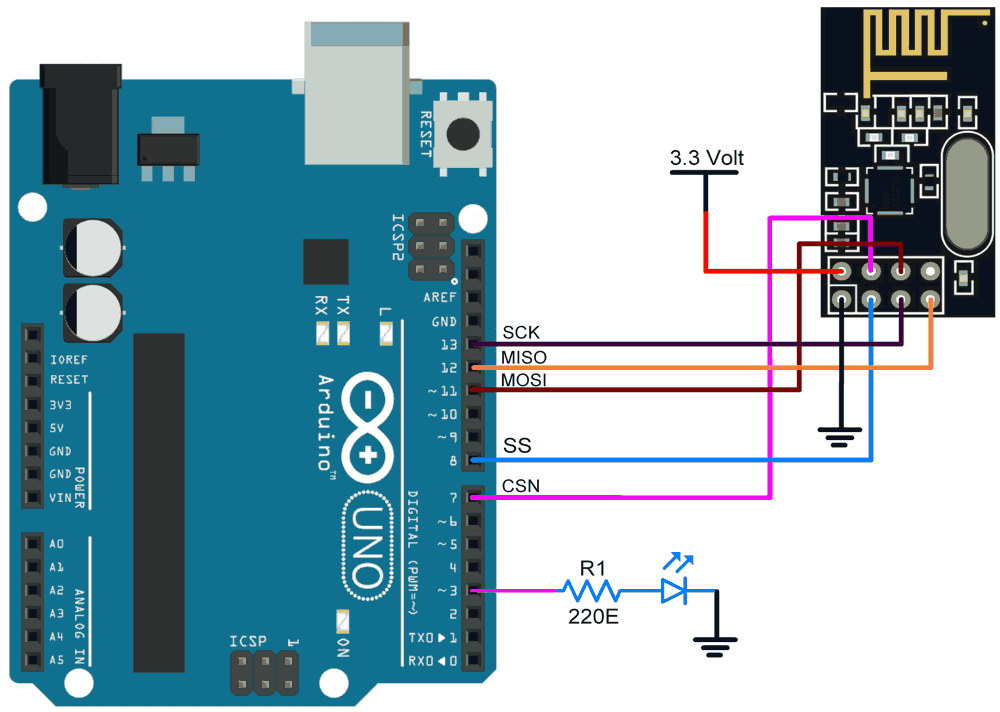
Connection Diagram of nRf24L01 as Transmitter with Arduino
nRF24l01 Connections to Arduino UNO
| nRF24L01 | Arduino UNO |
| VCC | 3.3V |
| GND | GND |
| SCK | D13 |
| MISO | D12 |
| MOSI | D11 |
| CSN | D7 |
| CE | D8 |
Connection Diagram of nRf24L01 as Receiver with Arduino
nRF24l01 Connection to the Arduino UNO
| nRF24L01 | Arduino UNO |
| VCC | 3.3V |
| GND | GND |
| SCK | D13 |
| MISO | D12 |
| MOSI | D11 |
| CSN | D7 |
| CE | D8 |
In this tutorial, we are going to control the brightness of LED connected to receiver Arduino using POT connected to transmitter Arduino.
Transmit and Receive the data using nRf24L01 and Arduino Uno
Here, we will be using TMRh20’s RF24.h and Paul Stoffregen’s SPI.h library from GitHub.
Download RF24 library from here.
Download SPI library from here.
Extract these libraries and add it to the libraries folder path of Arduino IDE.
For information about how to add a custom library to the Arduino IDE and use examples from it, refer Adding Library To Arduino IDE in the Basics section.
Once the library has been added to the Arduino IDE, open the IDE and open the example sketch you want from the list of examples from the library added.
nRf24L01 Transmitter Code with Arduino
//Adding Libraries
#include <SPI.h> /* to handle the communication interface with the modem*/
#include <nRF24L01.h> /* to handle this particular modem driver*/
#include <RF24.h> /* the library which helps us to control the radio modem*/
#define pot_pin A0 /*Variable pin of POT is to be connected to analog pin 0 i.e.A0*/
RF24 radio(7,8); /* Creating instance 'radio' ( CE , CSN ) CE -> D7 | CSN -> D8 */
const byte Address[6] = " 00009 " ; /* Address to which data to be transmitted*/
void setup() {
// put your setup code here, to run once:
Serial.begin(9600);
pinMode(pot_pin,INPUT); /* Setting A0 (POT pin) as input*/
radio.begin (); /* Activate the modem*/
radio.openWritingPipe (Address); /* Sets the address of transmitter to which program will send the data */
}
void loop() {
// put your main code here, to run repeatedly:
radio.stopListening (); /* Setting modem in transmission mode*/
int value = analogRead(pot_pin); /*Reading analog value at pin A0 and storing in varible 'value'*/
int data = map( value , 0 , 1023 , 0 , 255 ); /* Convering the 10 bit value to 8 bit */
radio.write(&data, sizeof(data)); /* Sending data over NRF 24L01*/
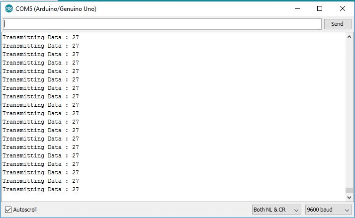
Serial.print("Transmitting Data : ");
Serial.println(data); /* Printing POT value on serial monitor*/
}
nRf24L01 Receiver Code with Arduino
//// Adding Libraries
#include <SPI.h> /* to handle the communication interface with the modem*/
#include <nRF24L01.h> /* to handle this particular modem driver*/
#include <RF24.h> /* the library which helps us to control the radio modem*/
#define led_pin 3 /* Connect LED anode to D3 (PWM pin) */
RF24 radio(7,8); /* Creating instance 'radio' ( CE , CSN ) CE -> D7 | CSN -> D8 */
const byte Address[6] = "00009"; /* Address from which data to be received */
void setup() {
// put your setup code here, to run once:
Serial.begin(9600); /*Setting baudrate of Serial Port to 9600*/
radio.begin(); /* Activate the modem*/
radio.openReadingPipe(1, Address); /* Sets the address of receiver from which program will receive the data*/
}
void loop() {
// put your main code here, to run repeatedly:
radio.startListening(); /*Setting modem in Receiver mode*/
if (radio.available())
{
while (radio.available()) /* Loop until receiving valid data*/
{
int rx_data = 0 ; /* Variable to store received data */
radio.read(&rx_data, sizeof(rx_data));/* Read the received data and store in ' rx_data ' */
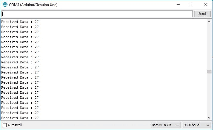
Serial.print("Received Data : ");
Serial.println(rx_data); /* Print received value on Serial Monitor */
analogWrite(led_pin , rx_data);/* Write received value to PWM pin 3 to which LED is connected */
}
}
else
{
Serial.println("Not Receiving !!!"); /* If not receiving valid data print " Not Receiving !!! " on Serial Monitor */
}
///// END OF LOOP //////
}
Functions Used in nRf24L01 Code
RF24 radio(7,8)- This function is used to set the CE and CSN pin connection for nRF24l01.
- It connected CE pin to D7 and CSN pin to D8 of Arduino UNO.
const byte Address[6] = " 00009 "- This function is used to define the address of nRF24l01.
radio.begin ()- This function activates the modem.
radio.write(&data, sizeof(data)) - This function is used to write or transmit the data.
- &data transmit the data presents at the address location of “
data”. sizeof(rx_data)automatically calculates the number of bytes in a “rx_data” string.
radio.read(&rx_data, sizeof(rx_data));- This function is used to read the received data.
- &rx_data receive and store the data at the address location of “
rx_data”. sizeof(rx_data)automatically calculates the number of bytes in a “rx_data” string.
nRf24L01 Transmitter Output Serial Monitor
nRf24L01 Receiver Output Serial Monitor
Components Used |
||
|---|---|---|
| Arduino UNO Arduino UNO |
X 1 | |
| Arduino Nano Arduino Nano |
X 1 | |
| nRF24L01 2_4GHz Transceiver nRF24L01+ is a single chip RF transceiver for 2.4GHz ISM band. |
X 1 | |