Introduction to GPIO
General-Purpose Input Output (GPIO) is a digital pin of an IC. It can be used as input or output for interfacing devices.
If we want to read the switch’s state, sensor data, etc then we need to configure it as input. And if we want to control the LED brightness, motor rotation, show text on display, etc then we need to configure it as output.
Arduino Uno GPIO Pin Diagram
Arduino Uno board has various digital IO pins which can be used for input/output devices. Following image shows the digital IO pins of Arduino Uno.
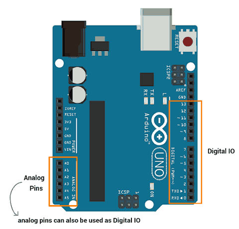
Arduino analog pins can also be used as digital input/output pins. Let’s see digital input, output of Arduino (ATmega).
Digital Output
Arduino (ATmega) digital pins can be configured as output to drive output devices. We have to configure these pins to use as output.
To configure these pins, pinMode() function is used which set direction of pin as input or output.
- pinMode(pin no, Mode)
This function is used to configure GPIO pin as input or output.
pin no number of pin whose mode we want to set.
Mode INPUT, OUTPUT or INPUT_PULLUP
E.g. pinMode (3, OUTPUT) //set pin 3 as output
These Arduino (ATmega) pins can source or sink current up to 40 mA which is sufficient to drive led, LCD display but not sufficient for motors, relays, etc.
Note: While connecting devices to Arduino output pins use resistor. If any connected device to Arduino withdraw current more than 40 mA from the Arduino then it will damage the Arduino pin or IC.
These pin produce output in terms of HIGH (5 V or 3.3 V) or LOW (0 V). We can set output on these pins using digitalWrite () function.
- digitalWrite (pin no, Output value)
This function is used to set output as HIGH (5 V) or LOW (0 V)
pin no number of a pin whose mode we want to set.
Output value HIGH or LOW
E.g. digitalWrite (3, HIGH)
Digital Input
To read data from senor or from any device/circuit, we need to configure digital pin as input. Arduino pin are set as digital input (default). So, there is no need to configure pin as input.
To configure pin as digital input, pinMode() function is used. We can read data from GPIO pin using digitalRead() function.
- digitalRead(pin)
It is used to read data from specified GPIO pin.
Digital Input with Pull-up Resistor
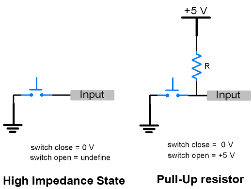
- Sometimes switching between one state to another or pins configured as input with nothing connected to them may arise situation of High-impedance state i.e. floating state. This state may report random changes in pin state.
- To avoid this state, there is option of adding pull-up (to +5V) or pull-down (to Gnd) resistor which helps to set the input to a known state. Following image show the high impedance (undefine) state and pull-up resistor.
- Arduino (ATmega) has in-built configurable pull-up resistor. These resistors enable using pinMode() with mode set to INPUT_PULLUP. When connecting a device or sensor to a pin configured as input with pull-up, the other end should be connected to ground.
e.g. pinMode (3, INPUT_PULLUP).
- We can configure input pull-up in another way too. If we set direction of pin as input and then write HIGH value on that pin will turn on the pull-up resistor. In other manner, if we write HIGH on pin configured as OUTPUT and then configure that pin as input will also enable the pull-up resistor.
e.g. pinMode (3, INPUT) //set pin as input
digitalWrite (3, HIGH) //setting high on input pin enables pullup
Blink LED Using Arduino
Let’s write a program for led blinking using Arduino Uno. Here, we will blink on-board LED of Arduino Uno which is connected to digital pin 13.
LED Blinking using Arduino Code
void setup()
{
  pinMode(13, OUTPUT);          // sets the digital pin 13 as output
}

void loop()
{
  digitalWrite(13, HIGH);       // sets the digital pin 13 on
  delay(1000);                  // waits for a second
  digitalWrite(13, LOW);        // sets the digital pin 13 off
  delay(1000);                  // waits for a second
}
Output of LED Blinking using Arduino Uno
Sequentially Turning ON-OFF LED using Arduino
Let’s turn ON-OFF led sequentially. Here, first we will turn four LED ON one by one which means LED1 will ON first then LED1 and LED2 will ON and so on. When at last all four leds will get ON then turn them off in reverse sequence one by one. That means turn LED4 OFF then turn LED3 OFF and so on.
Four LED’s are connected to pin 0 – 3 of Arduino Uno.
Note: While uploading program to Arduino just remove the connection of pin 0 and 1 as they are RXD and TXD pin which are used by serial communication for program uploading. When program uploaded successfully, then connect the connection of pin 0 and 1.
Sequential LED ON-OFF code using Arduino uno
void setup() {

//set gpio pin {0,1,2,3} as output
pinMode(0, OUTPUT);
pinMode(1, OUTPUT);
pinMode(2, OUTPUT);
pinMode(3, OUTPUT);
}

void loop() {
  //turn LED ON one by one
  for(int i=0;i<4;i++){
    digitalWrite(i, HIGH);
    delay(1000);
  }

  //turn LED OFF one by one
  for(int i=3;i>=0;i--){
    digitalWrite(i, LOW);
    delay(1000);
  }
}
Output Video
Control LED with Switch using Arduino
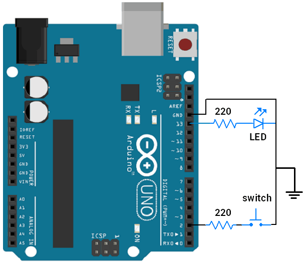
Let’s control LED ON-OFF using switch interfaced to Arduino Uno.
LED and Switch connection diagram with Arduino Uno
Control LED with a Switch using Arduino Code
int pushButton = 2;
int LED = 13;

void setup() {
  // make the pushbutton's pin an input:
  pinMode(pushButton, INPUT_PULLUP);  //configure pin as input with pullup enabled
  pinMode(LED, OUTPUT);               //configure pin as output
}

void loop() {
  // read the input pin:
  int buttonState = digitalRead(pushButton);

  digitalWrite(LED, (!(buttonState))); //turn len on when switch pressed

  delay(1);        // delay in between reads for stability
}
Video
For more implementations,
Components Used |
||
|---|---|---|
| Arduino UNO Arduino UNO |
X 1 | |
| Arduino Nano Arduino Nano |
X 1 | |
| LED 5mm LED 5mm |
X 1 | |
| Breadboard Breadboard |
X 1 | |