Introduction
Bootloader, is basically the initial piece of code which runs whenever any micro-controller is powered up or resets. It is similar to the concept of BIOS which run in our PC at the time we power up it. In case of BIOS, it waits for a user input for changing Boot options/settings. If it does not get any such inputs, it will start with the pre-installed OS.
A similar thing happens with Arduino bootloader. Whenever the Arduino is powered up or reset, it looks for external inputs (for uploading new program). If it receives no such inputs, it starts executing the program that was uploaded last.
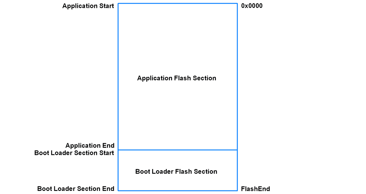
Arduino uses avr microcontrollers for their platforms which has program memory sections as shown in above figure. Boot Loader section is placed at the bottom of flash memory.
The bootloader program is written in the bootloader section, and the application program is written in the application section.
How Bootloader Starts
As we know that whenever a microcontroller is reset or is powered up, generally it starts program execution from the reset vector i.e. from 0x0000 program memory address.
We can change this reset vector address (0x0000) to bootloader section start address in case if we are using bootloader on the microcontroller. That means, whenever the microcontroller is get reset/powered up, it starts program execution from the bootloader section.
Arduino bootloaders do the same thing and execute the bootloader program when the microcontroller (used by Arduino) is reset/powered up i.e. the microcontrollers start execution of program from boot loader section’s start address.
If we refer AVR microcontrollers (which are used for arduino) datasheet we can see that Boot Reset Fuse can be programmed so that Reset Vector is pointing to the Boot Flash start address after reset as shown in below figure.
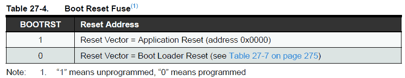
Hence, we can set the reset vector to the start of the bootloader section on power up/reset.
Need of a Bootloader
Most of the times, bootloaders in microcontrollers are used to simplify the uploading of programs to the microcontrollers. They can also be used for initializing IO devices connected to the microcontrollers before they begin the main application program.
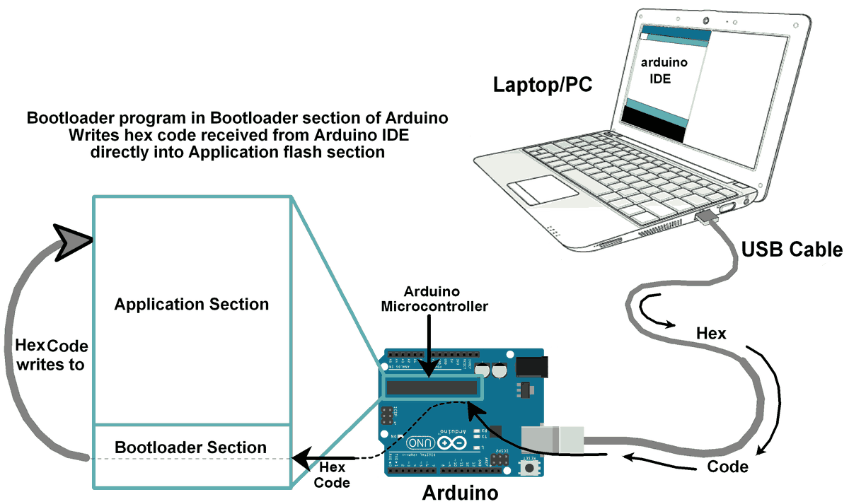
Arduino bootloaders use the simple serial communication (UART) to download the hex file of program and write it in application section.
Inside the Bootloader
Now let’s see in brief about how Arduino Bootloader is written and how it communicates with Arduino IDE while uploading programs.
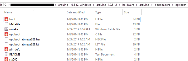
We can find arduino bootloader program at
arduino-version\hardware\arduino\bootloaders\optiboot
As shown in below figure.
The boot headerfile (boot.h) is included from avr toolchain. This is modified/optimised version of avr toolchain boot header file(<avr/boot.h>). You can find avr boot header file at arduino-version\arduino-1.0.5-r2\hardware\tools\avr\avr\include\avr
avr boot header file uses sts(which requires two machine cycle) instruction to access SPM register whereas boot header file used in arduino bootloader uses out (which requires only one machine cycle) instruction to access SPM register. This important optimisation is already mentioned in avr toolchain boot header file for smaller devices.
Boot header file contains the function related to write/read flash memory (in manner of page by page). Also, it contains the function for writing/reading fuse, lock, and signature bits.
stk500 header file (stk500.h) contains the STK500 commands which are used for reliable handshaking communication in between arduino and avrdude program while uploading hex file.
Pin definition header file (pin_defs.h) contains port definition for LED (arduino on-board LED) which is used as status LED blink while flashing the arduino.
optiboot.c file contains the main program flow of bootloader (i.e. receiving hex serially and writing it to program memory). Other files (boot.h, pin_defs.h, stk500.h) are included in optiboot.c file.
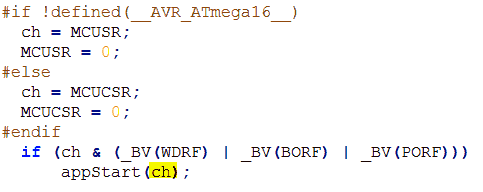
Optiboot program starts with MCUSR (MCU Status Register) status register which provides information about the reset source that caused reset. If reset source is not external (by pulling reset pin low), then it will directly start the application program. As shown in below figure, it will call appStart() function from where it jumps to direct 0x0000 reset address.
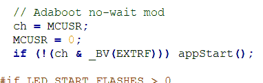
Note: that here MCUSR is cleared after use hence we cannot use it again for getting the reset source in our application program if we need. This is not an issue since we can modify the bootloader as per our requirement if we want.
If reset source is external (by pulling reset pin low) then it will avoid jump to application code directly and prepare for serial communication with avrdude running at PC/laptop to read hex file and flash it into program memory.
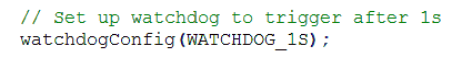
Watchdog is prepared for 1 second timeout in program to get reset if there is any error while uploading code or to get reset while program memory write completes.
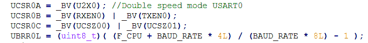
It will then initialize serial communication (here UART) to communicate with arduino IDE running at pc/laptop.
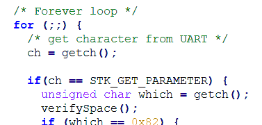
After above initializations, it starts its forever loop to read bytes (command/data byte) serially using protocol used by STK500.
Program memory is written/updated in page by page fashion. The page size varies according to the controller. For example, Atmega328/328P has a page size of 64 words (i.e. 128 bytes) whereas Atmega88A/88PA has a page size of 32 words (i.e. 64 bytes).
The process of writing program memory is carried out in page by page manner as follow.
- In above mentioned forever loop hex bytes coming serially from arduino uploader running at pc/laptop are first copied to the temporary data memory (say RAM).
- After copying page sized hex bytes in temporary dmemory'smory, program memory first page erase is processed.
- After erase of page, first it is filled (just fill not write) with hex bytes stored in temporary data memory.
- Then using SPM page write instruction, page write/update is successfully carried out.
- The above process of reading data from serial and then writing it to program memory in page by page fashion is carried out until complete hex bytes are written/updated in program memory.
- After completion of hex file write operation, opposite process is carried out i.e. reading from program memory and sending it serially to pc/laptop in page by page manner to verify whether hex file got written/updated in program memory or not.
Below is sample page write function which is already given in boot header file
#include <inttypes.h>
#include <avr/interrupt.h>
#include <avr/pgmspace.h>
void boot_program_page (uint32_t page, uint8_t *buf)
{
	uint16_t i;
	uint8_t sreg;
	// Disable interrupts.
	sreg = SREG;
	cli();
	eeprom_busy_wait ();
	boot_page_erase (page);  //erase page
	boot_spm_busy_wait ();      // Wait until the memory is erased.

	for (i=0; i<SPM_PAGESIZE; i+=2)
	{
		// Set up word from temp buffer.
		uint16_t w = *buf++;
		w += (*buf++) << 8;
		boot_page_fill (page + i, w);  //fill (page + i ) address with word
	}
	boot_page_write (page);     // Store/write buffer in flash page.
	boot_spm_busy_wait();       // Wait until the memory is written.
	// Reenable RWW-section again. We need this if we want to jump back
	// to the application after bootloading.
	boot_rww_enable ();
	// Re-enable interrupts (if they were ever enabled).
	SREG = sreg;
}
All above is basic general idea about how hex file gets written in program memory.The functions used in above program i.e. boot_page_fill (page address, word data), boot_page_write(page address), boot_spm_busy_wait()etc.all are available in boot header (boot.h) file which are written with inline assembly instructions.
How does a program residing at the bottom of the program memory itself manages to write into the program memory? i.e. how program in boot section writes into the application section. This is possible since avr microcontrollers provides a self-programming mechanism(SPM) for downloading and uploading code by the microcontroller itself. The Self-Programming can use any available data interface and associated protocol to read code and write (program) that code into the Program memory.
How arduino is programmed with its IDE
Arduino bootloader uses the serial protocol (UART) to download the program hex file from PC/laptop. At the PC/laptop side Arduino IDE is running which compiles the application program and sends its compiled hex code to the Arduino board over USB cable serially.
Arduino IDE uses the avrdude tool which is used to upload/download the code/data content to/from the ROM/EEPROM of AVR microcontrollers.
AVRDUDE (AVR Downloader Uploader) is a program for downloading and uploading the on-chip memories of Atmel's AVR microcontrollers. It can program the Flash and EEPROM, and supported by the serial programming protocol, it can also program fuse and lock bits.
The communication protocol from STK500 is used by avrdude to upload compiled hex file to arduino serially. This is the reason for why we include/use STK500 commands header file in bootloader program.
STK500 communication is used in between avrdude (running at pc/laptop side) and bootloader (running at arduino side) to write/read the hex file.
Now let’s first see how to upload bootloader program in boot section.
How to upload Bootloader first
To use bootloader, we need to first write/install bootloader into the bootloader section of program memory.
Generally, we program any IC before soldering it on PCB. Whereas many microcontroller manufacturers (e.g. Atmel, Microchip) provide specialized In System Programming (ISP) method known as In-Circuit Serial Programming (ICSP). In such methods ISP header is provided on board for flashing it with external programmer.
Arduino has on board ICSP header for programming as shown in below figure.
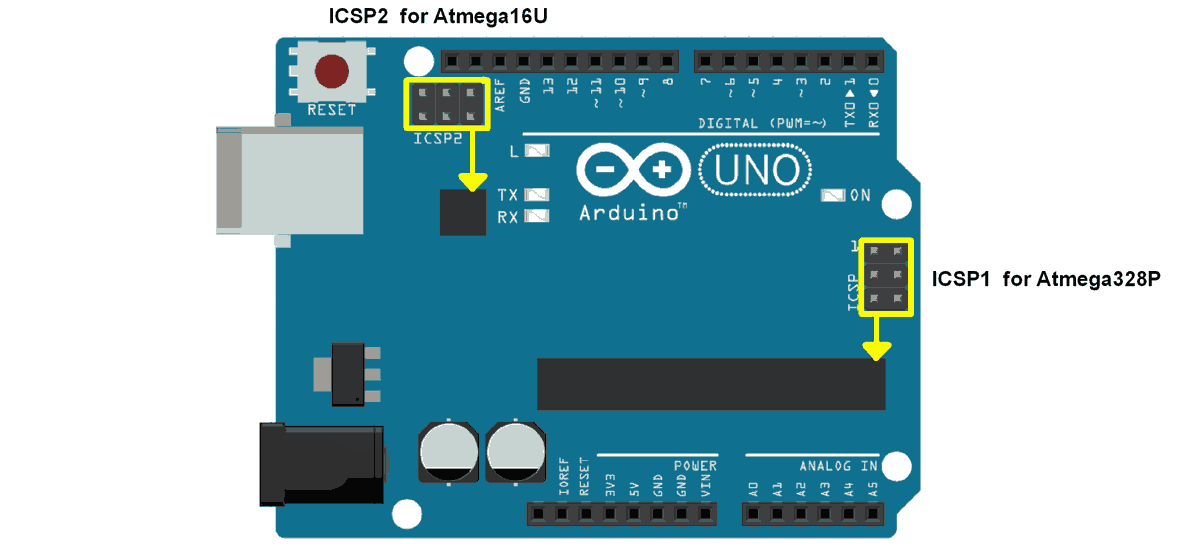
As shown in above figure Arduino UNO has two ICSP headers. One for the ATmega16U2 and one for the ATmega328. To flash the bootloader, we need to use ICSP header for the ATmega328.
We can build and flash arduino bootloader using Atmel Studio and USBasp (in circuit programmer). To know about how to build and flash hex file into avr microcontrollers refer Getting Started with Atmel Studio.
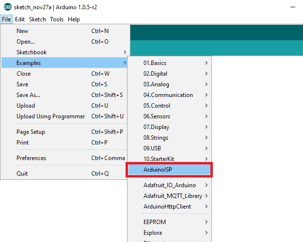
Also, we can flash bootloader using another Arduino i.e. if we have second arduino board we can use it as ISP programmer. Open Arduino IDE and open ArduinoISP example from its example menu as shown in below figure.
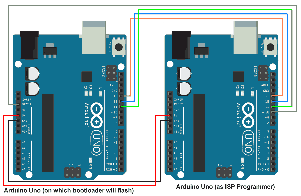
and upload ArduinoISP program on Arduino board which we are using as ISP Programmer. Now connect (as shown in below figure) this arduino isp programmer to arduino board which is to be programmed.
Select Arduinoboard (ISP programmer) on port and select programmer as “Arduino as ISP” from tools option as shown in below figure.
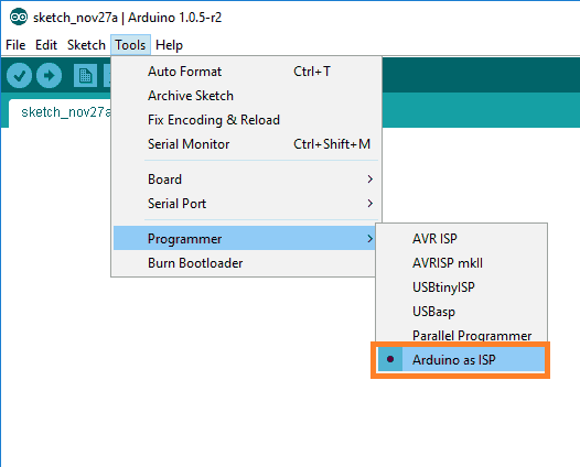
Next just click on “Burn Bootloader” option from tools menu (seen in above image). Wait for bootloader burning process completion. We can see the LED blinks while bootloader burning process is on.
On successfully burning of bootloader, Arduino board (on which bootloader is burned) is ready to be programmed.
How to modify Arduino Bootloader
There is also a modified version of Arduino Bootloader available which comes with few proper functions and one major change. The change is that the reset cause (MCUSR status register) is passed from bootloader program to the application program through r2 register. It is passed through app_start() function as shown in below figure.
We have attached this modified version of Arduino (atmega328P) bootloader Atmel Studio 7 project file in attachment section (at the end of this doc). Try it as it is or write it with your own way.
There are many options so that we can modify the provided bootloader program as per our requirement. For example, arduino bootloader uses UART serial communication to read hex file from pc/laptop. We can also use other available serial communication options like SPI, I2C serial communication. Using these communications, we can read hex file from external source (e.g. memory card, eeprom).
Bootloader Section Size
There is another important thing about bootloader, how much size is available in microcontroller for bootloader section.
If we take example of Arduino, then we can see that the bootloader size is user selectable. E.g. Arduino UNO which uses Atmega328P avr microcontroller has bootloader size that is selectable as per given in their datasheet.
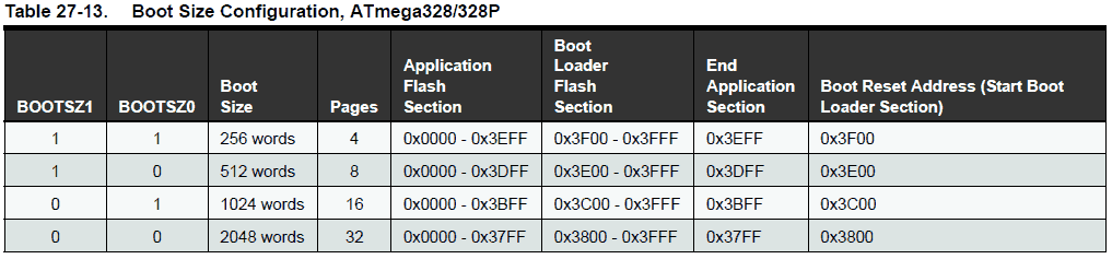
As shown in above figure of boot configuration we can see their boot section size is selectable. Boot size is given in words which is half of the size in bytes i.e. 256 words means 512 bytes.
Boot reset start address is also selectable sets as per boot size configuration i.e. if we select 256 words size for boot section then we need to write bootloader program which will fit in only 256 words (512 bytes) of memory and its start address will be 0x3F00 (0x7E00 in bytes). Hence bootloader program should be within 0x3F00 to 0x3FFF (512 Bytes).
Atmel Studio Project Properties settings while designing bootloader
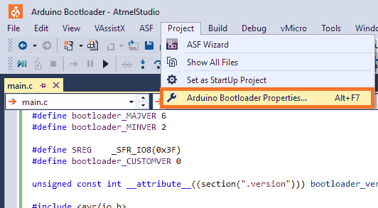
When we create new project for Arduino bootloader in Atmel Studio just make some important changes in their properties for optimization purpose. First open project property window from Project menu as shown in below figure.
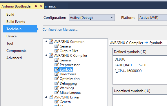
Then project properties will pop up. Then go to Toolchain ->Symbols in AVR/GNU Compiler to define symbol if any. Here we are defining baud rate as 115200 and frequency as 16000000 Hz in this section as shown in below figure.
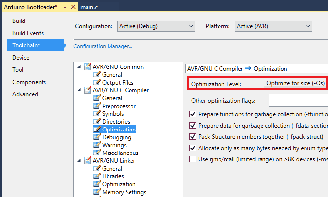
Then go to optimization option, just second after Symbols option, and select optimization Level to “Optimize for size (-Os)” which will optimize our code for minimum size.
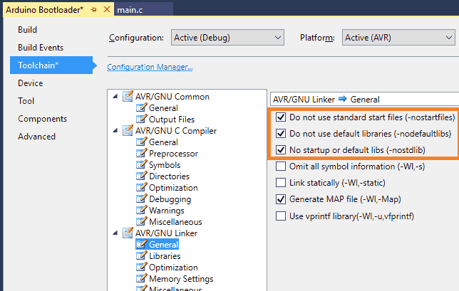
Now navigate to general option in AVR/GNU Linker and tick mark the first three labels since we are not using them in bootloader. Those options are
- Do not use standard start files (-nostartfiles)
- Do not use default libraries (-nodefaultlibs)
- No startup or default libs (-nostdlib)
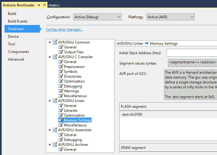
Now the important point is memory settings (option in AVR/GNU Linker) where we can define the start address of flash memory segments, SRAM segments, eeprom segments and initial stack address.
For arduino bootloader we are selecting boot configuration size of 256 words (512 bytes). After every reset/power failure controller will need to jump to bootloader section first. So, we need to define the flash segment start address to the bootloader start address. So just define flash segment with .text=0x3F00 address as shown in below figure.
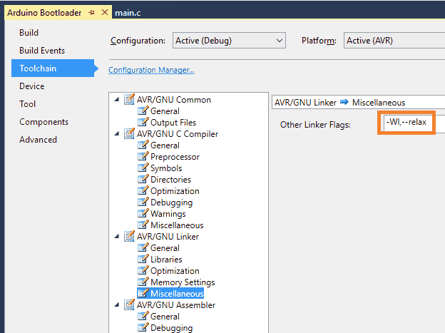
Also, we are adding linker flags which are used in relaxation of branches i.e. nearby functions (say in range of +2k to -2k from current program memory address) will be called using RCALL instruction instead of direct CALL instruction which will save additional cycle required in call routine.
Components Used |
||
|---|---|---|
| Arduino UNO Arduino UNO |
X 1 | |
| Arduino Nano Arduino Nano |
X 1 | |