Description
.jpg)
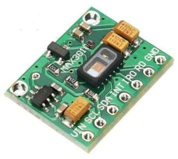
- The MAX30100 Pulse Oximeter is a medical device that is used to measure blood oxygen saturation levels, heart rate, and pulse strength.
- It uses a non-invasive method to measure oxygen saturation levels in the blood.
- This module has a pair of LEDs (Light Emitting Diode) that emit a monochromatic red light at a wavelength of 660nm and infrared light at a wavelength of 940nm.
- As the photodiode emits light, it falls on the finger and gets absorbed by the oxygenated blood rest light is reflected through the finger and falls on the detector.
- The detector detects and processes the signals and gives the output.
- The MAX30100 sensor works on the I2C Serial Communication protocol.
MAX30100 module Specification
- Operating voltage of the module is 1.7V to 3.3V.
- Supply current of 1200uA.
- The operating temperature range of the module is -40C to +85C.
- LED Current range 0mA to 50 mA.
- LED Pulse width range from 200us to 1.6ms
MAX30100 Sensor Pinout
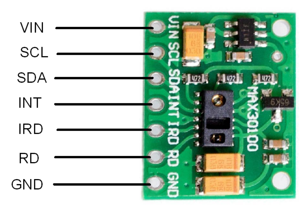
MAX30100 Pin Description
- VIN: Power supply pin connects in the range of
- GND: Connect to Supply ground.
- SCL: Serial Clock pin for I2C Serial Communication.
- SDL: Serial Data pin for I2C Serial Communication.
- INT: Active Low Interrupt pin.
- IRD: IR LED Cathode and LED Driver Connection pin.
- RD: Red LED Cathode and LED Driver Connection pin.
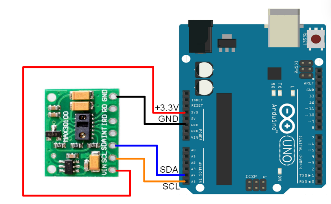
MAX30100 Hardware Connection with Arduino
Read Heart Rate using MAX30100 and Arduino
To find the heart rate (BPM) and Oxygen Saturation (SpO2) using MAX30100, we will use the I2C communication protocol and display the readings on the serial monitor of Arduino IDE.
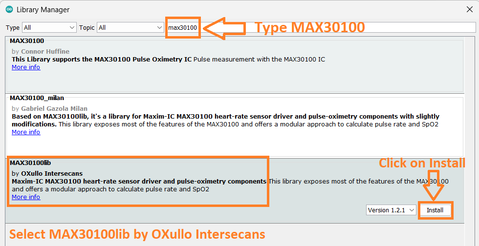
For the interface, we will use.MAX30100lib by OXullo Intersecans. We can install it from Arduino IDE Library Manager by searching max30100 in the search box.
Open the Arduino IDE and navigate to Sketch -> Include Library -> Manage Libraries…
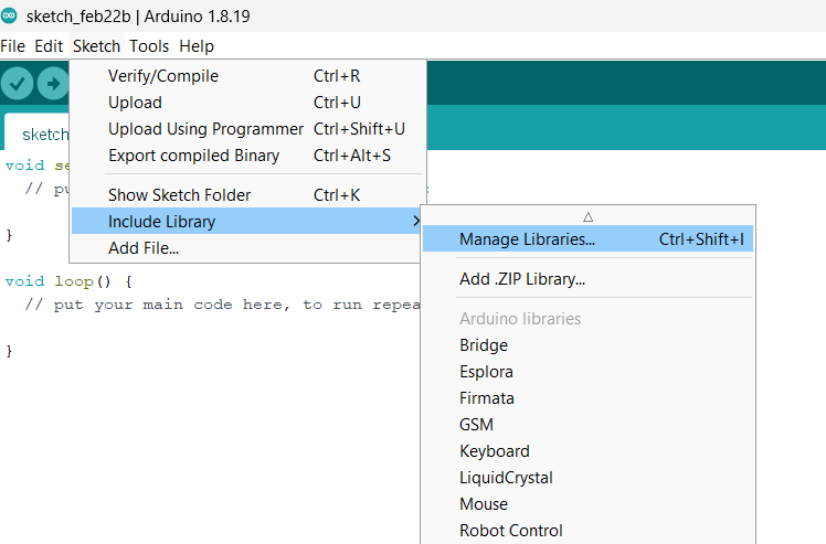
The library Manager window will pop up. Now type MAX30100 into the search box and click Install option to install version 1.2.1 or higher.
Now open an example of the MAX30100lib dashboard. To open it navigate to File -> Examples -> MAX30100lib -> MAX30100_Minimal
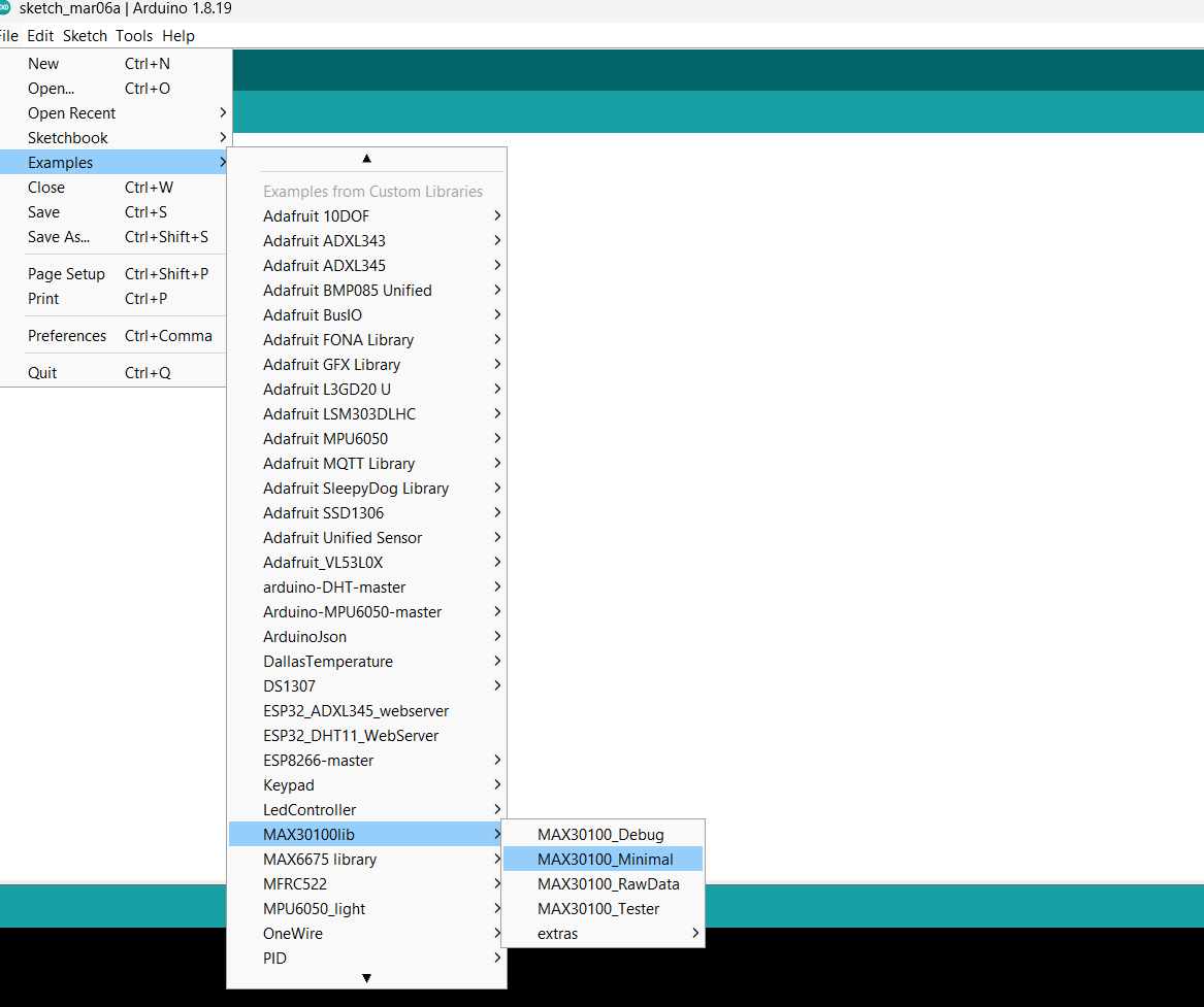
Here we have used the same example below
Code for MAX30100 with Arduino
/*
Arduino-MAX30100 oximetry / heart rate integrated sensor library
Copyright (C) 2016  OXullo Intersecans <[email protected]>

This program is free software: you can redistribute it and/or modify
it under the terms of the GNU General Public License as published by
the Free Software Foundation, either version 3 of the License, or
(at your option) any later version.

This program is distributed in the hope that it will be useful,
but WITHOUT ANY WARRANTY; without even the implied warranty of
MERCHANTABILITY or FITNESS FOR A PARTICULAR PURPOSE.  See the
GNU General Public License for more details.

You should have received a copy of the GNU General Public License
along with this program.  If not, see <http://www.gnu.org/licenses/>.
*/

#include <Wire.h>
#include "MAX30100_PulseOximeter.h"

#define REPORTING_PERIOD_MS     1000

// PulseOximeter is the higher level interface to the sensor
// it offers:
//  * beat detection reporting
//  * heart rate calculation
//  * SpO2 (oxidation level) calculation
PulseOximeter pox;

uint32_t tsLastReport = 0;

// Callback (registered below) fired when a pulse is detected
void onBeatDetected()
{
    Serial.println("Beat!");
}

void setup()
{
    Serial.begin(115200);

    Serial.print("Initializing pulse oximeter..");

    // Initialize the PulseOximeter instance
    // Failures are generally due to an improper I2C wiring, missing power supply
    // or wrong target chip
    if (!pox.begin()) {
        Serial.println("FAILED");
        for(;;);
    } else {
        Serial.println("SUCCESS");
    }

    // The default current for the IR LED is 50mA and it could be changed
    //  by uncommenting the following line. Check MAX30100_Registers.h for all the
    //  available options.
    // pox.setIRLedCurrent(MAX30100_LED_CURR_7_6MA);

    // Register a callback for the beat detection
   pox.setOnBeatDetectedCallback(onBeatDetected);
}

void loop()
{
    // Make sure to call update as fast as possible
    pox.update();

    // Asynchronously dump heart rate and oxidation levels to the serial
    // For both, a value of 0 means "invalid"
    if (millis() - tsLastReport > REPORTING_PERIOD_MS) {
        Serial.print("Heart rate:");
        Serial.print(pox.getHeartRate());
       Serial.print("bpm / SpO2:");
        Serial.print(pox.getSpO2());
        Serial.println("%");
 tsLastReport = millis();
}
}- Now upload the code on the Arduino board.
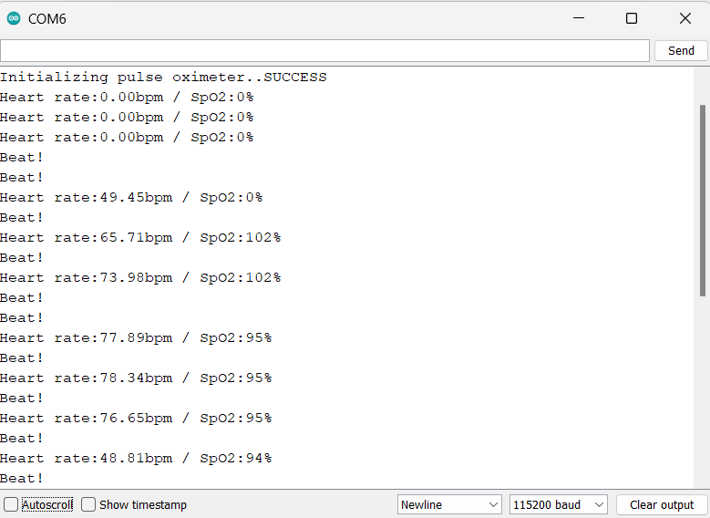
- After uploading the code open the serial monitor and set the baud rate to 115200 to see the output.
Output on the serial monitor
MAX30100 Not Working? Let’s see how to fix it.
The MAX30100 module is very famous among hobbyists, but the module has a serious design problem. Let’s see how to fix this issue.
There are two methods to fix this issue, both methods we have tested in our lab which are shown below.
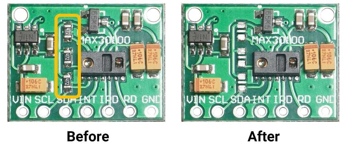
Method 1(Tested)
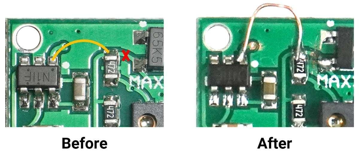
- Disconnect the 4.7kΩ pull-up resistors from the 1.8V supply voltage by cutting the trace along the red line.
- Now pulled up all 4.7kΩ resistors to 3.3V by connecting using a piece of wire along the yellow line, as shown in the below diagram.
Below are the images which show the before and after connection.
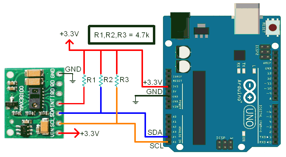
Method 2 (Tested)
The second method is to remove all 4.7k pull-up resistors and use the external pull resistor on SCL, SDA, and INT signal lines later.
After removing the resistor connect the MAX30100 to the Arduino as shown in the below diagram.
Let’s understand the code
At the top, we have to initialize the libraries.
#include <Wire.h>
#include "MAX30100_PulseOximeter.h"
Now we will define the delay using REPORTING_PERIOD_MS and an object pox is created for the PulseOximeter class.
#define REPORTING_PERIOD_MS     1000
PulseOximeter pox;
A variable tsLastReport is created with the data type of uint32_t for storing the last beat time.
uint32_t tsLastReport = 0;Now in the function onBeatDetected(), we will print “Beat” as the sensor detects the finger above it.
void onBeatDetected()
{
    Serial.println("Beat!");
}
In the setup function
We have set the baud rate as 115200 in the setup function.
Here, we have applied an if condition to detect the module and print its status of it.
Serial.begin(115200);
if (!pox.begin()) {
        Serial.println("FAILED");
        for(;;);
    } else {
        Serial.println("SUCCESS");
    }
}
Now this is the important function to set the IR LED current using setIRLedCurrent() function.
The below code line set the current of 7.6mA for the IR LED.
pox.setIRLedCurrent(MAX30100_LED_CURR_7_6MA);The default library IR LED current is set to 50mA which can cause the problems like LED not turning ON, Getting FAILED message on the serial monitor. At that time, change the LED current to a lower value.
Here are the other possible values you can use on the setIRLedCurrent() function.
- MAX30100_LED_CURR_0MA
- MAX30100_LED_CURR_4_4MA
- MAX30100_LED_CURR_7_6MA
- MAX30100_LED_CURR_11MA
- MAX30100_LED_CURR_14_2MA
- MAX30100_LED_CURR_17_4MA
- MAX30100_LED_CURR_20_8MA
- MAX30100_LED_CURR_24MA
- MAX30100_LED_CURR_27_1MA
- MAX30100_LED_CURR_30_6MA
- MAX30100_LED_CURR_33_8MA
- MAX30100_LED_CURR_37MA
- MAX30100_LED_CURR_40_2MA
- MAX30100_LED_CURR_43_6MA
- MAX30100_LED_CURR_46_8MA
- MAX30100_LED_CURR_50MA
Note, The brighter LED reaches deeper into your skin. So, you can set it according to it.
An important function is called in the setup function which is setOnBeatDetectedCallback().
The function registers the callback function.
pox.setOnBeatDetectedCallback(onBeatDetected);
In the Loop function
We are using the update() function for getting the updated data from the sensor.
pox.update();Functions such as getHeartRate() and getSpO2(), we receive the data on heart rate and the SpO2 percentage.
The sensor data would be printed on Serial Monitor every second as the REPORTING_PERIOD_MS is set to 1000.
Here we are using millis function instead of the delay function because millis function executes an instruction for a specific time in microseconds whereas the delay function stops the code for a specific time.
Now we will print the Heart rate and SpO2 value on the serial monitor.
if (millis() - tsLastReport > REPORTING_PERIOD_MS) {
        Serial.print("Heart rate:");
        Serial.print(pox.getHeartRate());
        Serial.print("bpm / SpO2:");
        Serial.print(pox.getSpO2());
        Serial.println("%");
 tsLastReport = millis();
}
Components Used |
||
|---|---|---|
| MAX30100 Pulse Oximeter and Heart-Rate Sensor MAX30100 is an integrated pulse oximetry and heart-rate monitor sensor solution. |
X 1 | |
| Arduino UNO Arduino UNO |
X 1 | |
Downloads |
||
|---|---|---|
|
|
MAX30100_Minimal | Download |