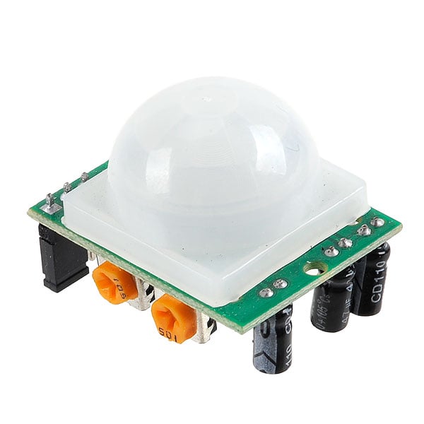
PIR Motion Sensor
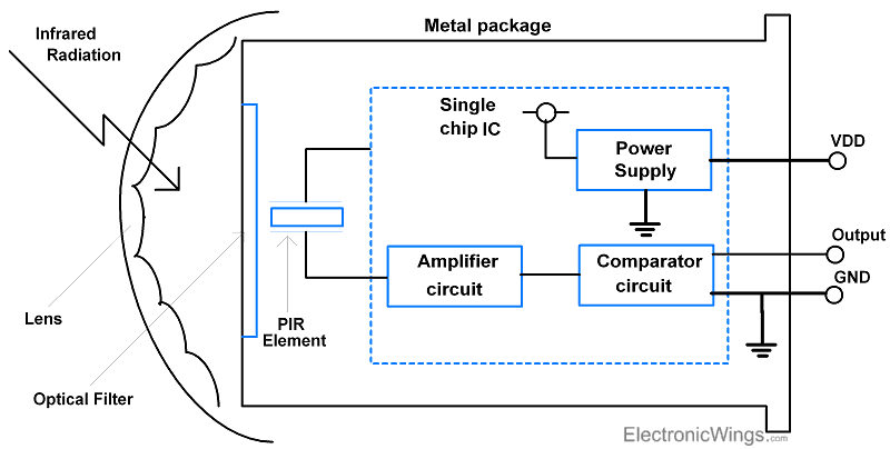
PIR sensor detects infrared heat radiations. It can be used to detect the presence of living objects that emit infrared heat radiation.
The PIR sensor is split into two slots. The two slots are connected to a differential amplifier.
Whenever a stationary object is in front of the sensor, the two slots receive the same amount of radiation and the output is zero.
Whenever a moving object is in front of the sensor, one of the slots receives more radiation than the other slot. This makes the output swing high or low.
This change in output voltage is a result of the detection of motion.
For more information on the PIR sensor and how to use it, refer to the topic PIR sensor in the sensors and modules section.
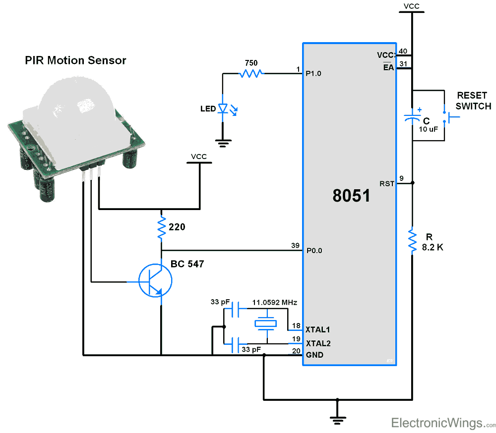
PIR Sensor Connection with 8051
Note:
- PIR sensor: Never keep PIR Sensor close to the Wi-Fi antenna, ESP32, or NodeMCU.
- PIR (Passive Infrared) sensor close to a WiFi antenna impacts the sensor's performance.
- PIR sensors detect changes in infrared radiation for motion detection.
- WiFi signals emit electromagnetic radiation that can interfere with the PIR sensor. Which causes false detection.
- So always keep the PIR sensor and WiFi antenna as far apart as possible.
- Also, you can try to shield the PIR sensor from the WiFi signal. This can be done by using metal shields or Faraday cages around the PIR sensor.
Example
- Let’s design a small application in which LED will turn ON when motion is detected.
- To do this, interface the PIR motion sensor with 8051.
- As shown in the Circuit Diagram, the output pin of the PIR motion Sensor is connected to the PORT0.0 pin.
- To get proper levels (0 and 5) at the 8051 input pin which is used to read the PIR sensor, the transistor is used.
- As the transistor is used, the P0.0 pin goes Low indicates the motion is detected and the LED will turn ON.
- According to the mode of Operation, If a High on this pin is detected, which means either motion is absent or the Period of Trigger is over and will Turn OFF the LED.
- Here we configure the module in repeatable trigger mode.
Note: After powering the module it needs about 30-50 secs to warm up in order to function properly.
Code for PIR Sensor using 8051
/*
 * PIR Motion sensor interface with 8051
 * http://www.electronicwings.com
 */


#include <reg51.h>

sbit Motion_detection=P0^0;	/* Read PIR sensor's data on this pin */
sbit LED=P1^0;				/* Connect LED to the PORT1.0 pin */


void MSdelay(unsigned int val);

void main(void)
{
	P1=0;			/* Initially LED turned OFF*/
	MSdelay(3000);	/* Power-on delay for PIR */
	while(1)
	{
		if(Motion_detection==1)  /* Check for human motion */
		LED = 0;	/* LED turn OFF for No motion */
		else
		LED = 1;	/* LED turn ON if motion is detected */
	}
}
void MSdelay(unsigned int val)
{
     unsigned int i,j;
        for(i=0;i<=val;i++)
            for(j=0;j<112;j++);	/* Delay of 1 ms for 11.0592MHz Frequency */
}
Video of PIR Motion Sensor Working with 8051
Components Used |
||
|---|---|---|
| PIR Sensor PIR motion sensors sense the Infrared signal radiated from moving objects including human or animal body. It is generally used to detect the presence of human or animal motions. |
X 1 | |
| LED 5mm LED 5mm |
X 1 | |
| Breadboard Breadboard |
X 1 | |
| 8051 AT89c51 8051 AT89c51 |
X 1 | |
Downloads |
||
|---|---|---|
|
|
8051_PIR_Interfacing_Keil_Project | Download |