Introduction to Power Saving Mode in 8051
Power down and Idle mode features are used to save power in microcontrollers. 8051 has an inbuilt power-saving feature which is useful in embedded applications where power consumption is the main constraint.
8051 microcontroller has two power-saving modes,
- Power Down Mode
- Idle Mode
Difference Between Power Down & Idle Mode
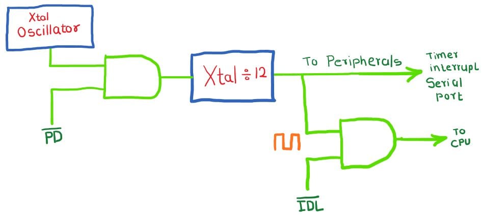
As shown in the above figure of 8051 power control logic, two control bits are there, IDL and PD, which are used for Idle and Power-down mode respectively.
In Power Down mode, the oscillator clock provided to the system is OFF i.e. CPU and peripherals clock remains inactive in this mode.
In Idle Mode, only the clock provided to the CPU gets deactivated, whereas the peripherals clock will remain active in this mode.
Hence power saved in power-down mode is more than in idle mode.
The below table shows the power supply current required for 8051 family controllers in Normal (Active), Idle and Power-down mode.
| 8051 Controllers | Operating Oscillator Frequency Fosc. | Current required in Normal mode | Current required in Idle mode | Current required in Power Down mode |
|---|---|---|---|---|
| AT89S51 | 12 MHz | 25mA | 6.5mA | 50uA |
| P89V51RD2 | 12 MHz | 11.5mA | 8.5mA | 80-90uA |
| DS80C323 | 18 MHz | 10mA | 6mA | 0.1uA for BGR enabled. 40uA for BGR disabled. |
As per the above table, it is clear that power consumption in power-down mode is less than in Normal or idle mode.
8051 has a power control register for power control. Let's see the power control register.
PCON Register: Power control register
PCON (Power Control) register is used to force the 8051 microcontrollers into power-saving mode. The power control register of 8051 contains two power-saving mode bits and one serial baud rate control bit.

Bit 7 – SMOD
1 = Baud rate is doubled in UART mode 1, 2 and 3.
0 = No effect on Baud rate.
Bit 3:2 – GF1 & GF0:
These are general purpose bit for user.
Bit 1 – PD: Power Down
1 = Enable Power-Down mode. In this mode, the Oscillator clock turned OFF and both CPU and peripherals clock stopped. Hardware reset can cancel this mode.
0 = Disable Power-down mode.
Bit 0 – IDL: Idle
1 = Enable Idle mode. CPU clock turned off whereas internal peripheral module such as a timer, serial port, interrupts works normally. Interrupt and H/W reset can cancel this mode.
0 = Disable Idle mode.
Example of 8051 Idle mode
Let’s program the AT89C51 microcontroller to toggle Pin 0 of port 1 and force the microcontroller in Idle (sleep) mode by external interrupt1. We wake the microcontroller in normal mode by external interrupt0.
Programming steps
- Enable global and external0 and external1 interrupt. EA = 1, EXx = 1.
- Select interrupt type i.e. here interrupt on falling edge is selected ITx = 0.
- Set priority for interrupt if required through the IP register.
- The controller sleep mode can also be canceled by reset pin.
- Enable and disable idle (sleep) mode through the PCON register.
Here, sleep mode is enabled in external1 interrupt ISR and disabled in external0 interrupt ISR.
Program for 8051 Idle (sleep) mode
/*
 * 8051_Idle_mode
 * http://www.electronicwings.com
 */
#include <reg51.h>		/* Include x51 header file */
sbit test = P1^0;

void delay(k)			/* mSecond Delay function for Xtal 11.0592 MHz */
{
	int i,j;
	for (i=0;i<k;i++)
		for (j=0;j<112;j++);
}

void ExtInt_Init()		/* External interrupt initialize */
{
	IT0 = 1;      		/* Interrupt0 on falling edge */
	EX0 = 1;      		/* Enable External interrupt0 */
	IT1 = 1;      		/* Interrupt1 on falling edge */
	EX1 = 1;      		/* Enable External interrupt1 */
	EA  = 1;		/* Enable global interrupt */
	IP = 0x01;		/* Set highest priority for Ext. interrupt0 */
}

void External0_ISR() interrupt 0 /* External int0 ISR */
{
	PCON = 0x00;		 /* Disable Idle & Power Down mode */
}

void External1_ISR() interrupt 2 /* External int1 ISR */
{
	PCON = 0x01;		 /* Enable Idle mode */
				 /* Enable Power Down mode by PCON = 0x02; */
}

void main()
{
  ExtInt_Init();
	while(1)		 /* Toggle P1.0 continuous */
	{
		test = 0;
		delay(30);
		test = 1;
		delay(30);
	}

}
8051 Power Down Mode
To enable Power-down mode, set PD bit i.e. PCON = 0x02. Also, note that only a hardware reset can cancel this mode.
Note: according to Intel’s MCS-51 family user manual:
“The only exit from Power Down for the 80C51 is a hardware reset. Reset redefines all the SPRS, but does not change the on-chip RAM.”
But according to Atmel’s AT89s51 datasheet:
“Exit from Power-down mode can be initiated either by a hardware reset or by activation of an enabled external interrupt (INT0 or INT1). Reset redefines the SFRs but does not change the on-chip RAM.”
So AT89s51 controller can exit from power-down mode by reset as well as by external interrupts also.
Video
Components Used |
||
|---|---|---|
| 8051 AT89c51 8051 AT89c51 |
X 1 | |
| Mini Push Button Switch - 5-6mm Mini Push Button Switch - 5-6mm |
X 1 | |
| Breadboard Breadboard |
X 1 | |