Introduction
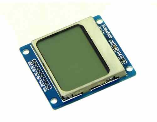
- Nokia5110 is a graphical display with 48x84 resolution which can be used for displaying images, text and various patterns.
- Nokia5110 is an 8 pin display which has internal display controller PCD8544 used to control / drive all 48 rows and 84 columns of the display.
- The display interfaces to the microcontroller through the serial peripheral interface i.e. (SPI).
Pin Description of Nokia5110
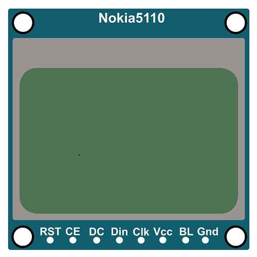
RST: RESET
This is an active low pin, used to reset the display.
CE: Chip Enable
Chip enable is active low pin.This is used to activate communication with the display.
DC: Data / Command
DC is used for sending data and command.
DC = 0, for sending commands to the display
DC = 1, for sending Data to the display
Din: Data in
Din pin is used for sending the data to the Nokia5110 display.
Clk: Clock
Clk is the clock pin of Nokia5110. This is the SCK pin (Serial Clock) of SPI protocol.
VCC & GND:
VCC and ground is the power source pins of Nokia5110.We have to provide 3.3 - 5V V as VCC.
BL: Backlight
BL is backlight pin. When this pin is active high then backlight of Nokia5110 will turn on. So we can directly connect it to VCC.
Specification of Nokia5110
- Resolution: 84 x 48 pixels
- Display color: Monochrome (Black and White)
- Display technology: PCD8544 controller, 84 x 48 pixel monochrome graphics display.
- Interface: Serial (SPI)
- Operating voltage: 3.3V to 5V
- Operating current: 0.1 mA (sleep mode), 40 mA (active)
- Brightness: adjustable with contrast pin
- Dimension: 48 x 43.5 x 5 mm.
Alternate options for Nokia5110
- OLED 128x64
- OLED 128x32
- GLCD 128x64
Nokia5110 Display Structure
In Nokia5110 display 84 columns and 48 rows are used.
Row Address (Y address): There are total 6 rows. Each row has height of 8 pixels. So row address given as Y address = 0 to 5.
Column Address (X Address): As display has total 84 pixels in each row, so X address = 0 to 83.
Example: Suppose we want to print the data on 3rd row at the middle then we have to provide address as Y address= 2 and X address= 41.
As display has total pixels= 48x84 = 4032, We can also provide the address of the pixels from 0 to 4031.
If we provide the address above the limit, it will not be considered by the display.
Commands for Nokia5110
Initialization
A reset pulse (low to high) must be applied to reset pin. The pulse width of low signal should not be less than 100 ms.All internal registers are reset by applying low pulse to RST pin.
Note that, device may damage if not properly reset.
Function Setting
For functional operation of Nokia5110 we have to use following bits.
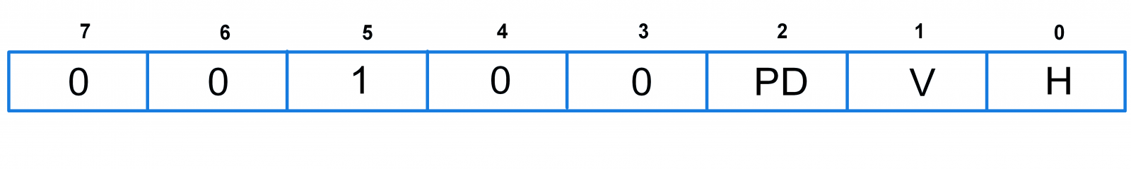
Bit 2- PD: Power down control bit
When PD is logic one then Nokia5110 is in power down mode.
Bit 1 - V:Vertical/Horizontal mode
1= Vertical addressing mode, display’s position address increases vertically i.e. Y address increment by 1 and when it reaches to 5(max. limit), x address increments by one and Y address rolls over to zero.
0= Horizontal addressing mode, display’s position address increases horizontally i.e. X address increments and when it reaches to 83(max. limit), Y address increments by one and X address rolls over to zero.
Bit 0 - H:Instruction set selection
When this bit is logic one then external instruction will get selected, otherwise internal instruction set will get selected.
Bit 5: This bit is always set to 1.
Display Control
This register is used to control the mode of operation of Display Nokia5110.
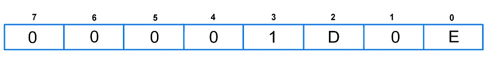
The table shows, meaning of display control register.
| D | E | Operation |
| 0 | 0 | Display Blank |
| 0 | 1 | Normal mode |
| 1 | 0 | All display segment on |
| 1 | 1 | Inverse mode |
Table: Meaning of D and E bit of display control register
Set Y address of RAM
Y address is used to address or point to the particular row (0-5)matrix. The Y address can vary from0 to 5 of display. The Y address can be defined using Y0, Y1 and Y2 bits of a register.
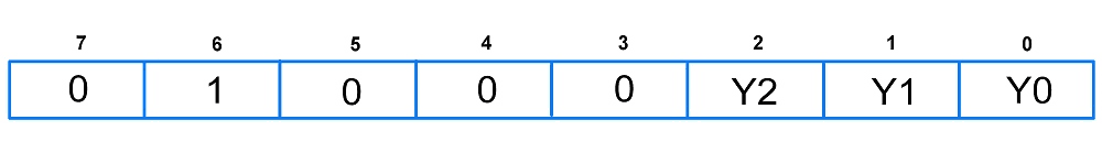
| Y2 | Y1 | Y0 | Position of Y-Address |
| 0 | 0 | 0 | Bank 0 |
| 0 | 0 | 1 | Bank 1 |
| 0 | 1 | 0 | Bank 2 |
| 0 | 1 | 1 | Bank 3 |
| 1 | 0 | 0 | Bank 4 |
| 1 | 0 | 1 | Bank 5 |
E.g. If we have to address row 3 or bank 3 then the Y address will be 0x43.
Set X address of RAM
X address is used to address or point the particular column matrix. The address value for X can vary from 00 to 83(column) of display. The X address is defined using X0 to X6 bits of register.
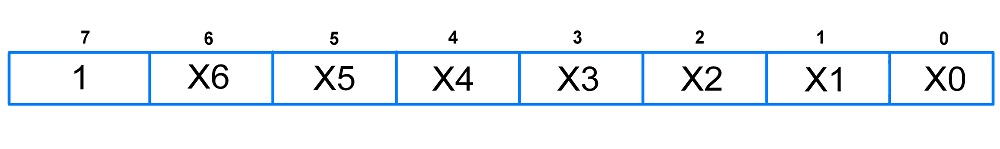
E.g. If we have to address 7th column of a row then the X address will be 0x87.
We have to send these X and Y addresses as command to the display by keeping DC = 0.
Temperature Control
Due to the temperature dependence of LCD viscosity, LCD controlling voltage VLCD must be increased at lower temperatures to maintain optimum contrast. The temperature coefficient of VLCD can be set using TC1 and TC0 bits in below register.

TC1:TC0: Temperature Coefficient select bits
| TC1 | TC0 | VLCD Temperature Coefficient |
|---|---|---|
| 0 | 0 | Temperature Coefficient 0 |
| 0 | 1 | Temperature Coefficient 1 |
| 1 | 0 | Temperature Coefficient 2 |
| 1 | 1 | Temperature Coefficient 3 |
Bias Value Setting
Following register is used to set Bias voltage level using BS2, BS1 and BS0 bits.

| BS2 | BS1 | BS0 | Recommended Mux Rate |
|---|---|---|---|
| 0 | 0 | 0 | 1:100 |
| 0 | 0 | 1 | 1:80 |
| 0 | 1 | 0 | 1::65 |
| 0 | 1 | 1 | 1:48 |
| 1 | 0 | 0 | 1:40/ 1:34 |
| 1 | 0 | 1 | 1:24 |
| 1 | 1 | 0 | 1:18/1:16 |
| 1 | 1 | 1 | 1:10/ 1:8/ 1:9 |
Image Showing on Display
As display has 84x48 pixel resolution, we can show binary image up to resolution 84x48.
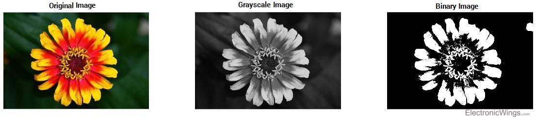
- To convert RGB image to binary image, first we have to convert it into Grayscale image, which has total 256 grey colour levels, where value for complete black is 0 and value for complete white is 255.
- The greyscale image can be converted in binary image by putting threshold value. If value of pixel is above the threshold it set to binary 1otherwise it changes to binary 0.
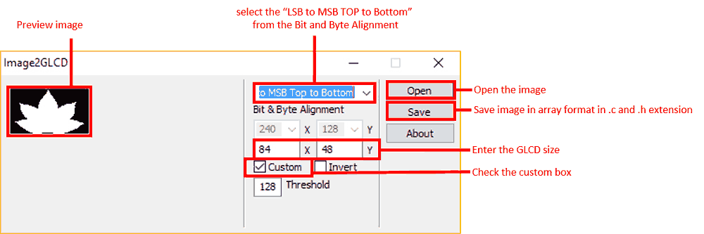
- Here we are using Image2GLCD software to get the binary image array.
- This software converts any type of image into the bit map image and provides us binary Image values in array format.
- The image2GLCD main window:
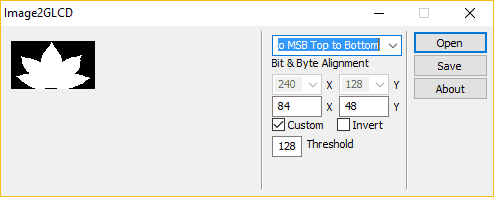
- In this software first step is to open the image file location and select the image which is to be displayed. Previewed image will be displayed on left side of software.
- Set the alignment to LSB to MSB TOP to Bottom”.
- Mark on the custom box and enter the GLCD pixel resolution size on X and Y boxes, where X indicate Width and Y indicate height.
- After all the arrangement click on save button then software will generate C file and header file of binary Image array.
Note: Sometimes the array value in generated header files are less than actual count. So please check this before displaying image. E.g. let’s say for 84x48 display, we need total 504 array values. But using this software we may get 496 or less than 504. So please insert remaining values in array manually.
You can download Image2GLCD application from below attachments.
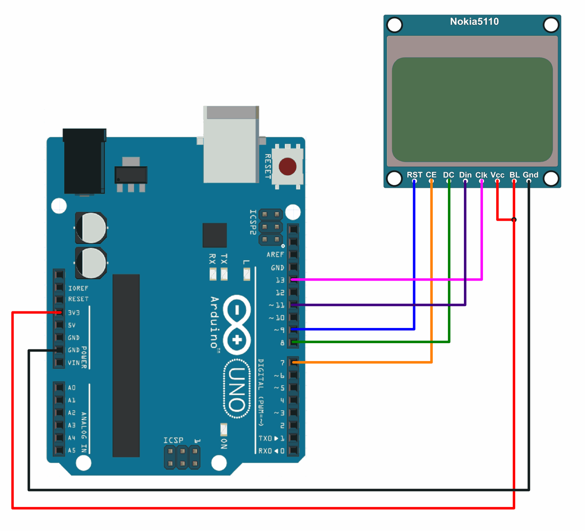
Nokia5110 Display interfacing with Arduino
Nokia5110 Display Code for Arduino
#include<SPI.h>
#include<Adafruit_GFX.h>
#include<Adafruit_PCD8544.h>
#include"images.h"

// Software SPI (slower updates, more flexible pin options):
// pin 13 - Serial clock out (SCLK)
// pin 11 - Serial data out (DIN)
// pin 8 - Data/Command select (D/C)
// pin 7 - LCD chip select (CS)
// pin 9 - LCD reset (RST)
Adafruit_PCD8544 display = Adafruit_PCD8544(13, 11, 8, 7, 9);

voidsetup()   {
 display.begin();

 display.setContrast(50);  /* Initializes the display. Sets SPI freq, SPI data mode, Bit order */

 display.clearDisplay();  /* Clears the screen and buffer */

 display.setCursor(13,5);  /* Set x,y coordinates */
 display.setTextSize(1); /* Select font size of text. Increases with size of argument. */
 display.setTextColor(BLACK); /* Color of text*/
 display.println("Electronic"); /* Text to be displayed */
 display.setCursor(28,15);
  display.println("Wings");
 display.display();
  delay(500);
  /* Draw rectangle with round edges. Parameters (x_co-ord,y-co-ord,width,height,color) */
 display.drawRoundRect(5, 25, 25, 13, 1, BLACK);
  /* Draw circle. Parameters (x_co-ord of origin,y-co-ord of origin,radius,color) */
 display.drawCircle(45, 34, 10, BLACK);
  /* Draw triangle. Parameters (x0,y0,x1,y1,x2,y2,width,color). (x0,y0), (x1,y1) and (x2,y2) are the co-ord of vertices of the triangle  */
 display.drawTriangle(60, 38, 70, 25, 80, 38, BLACK);
 display.display();
  delay(1000);
 display.clearDisplay();
  /* Draw image. Parameters (x_co-ord, y_co-ord, name of array containing image, width of image in pixels, height in pixels, color) */
 display.drawBitmap(0, 0, Arduino_Logo, 84, 48, 1);
 display.display();
  delay(1000);
}

voidloop(){
 display.clearDisplay();
 display.drawBitmap(0, 0, Smiley_1, 84, 48, 1);
 display.display();
  delay(300);
 display.clearDisplay();
 display.drawBitmap(0, 0, Smiley_2, 84, 48, 1);
  display.display();
  delay(300);
 display.clearDisplay();
 display.drawBitmap(0, 0, Smiley_3, 84, 48, 1);
 display.display();
  delay(300);
 display.clearDisplay();
 display.drawBitmap(0, 0, Smiley_4, 84, 48, 1);
 display.display();
  delay(300);
}
To run this code, you will need to install the Adafruit_GFX and Adafruit_PCD8544 libraries. You can do this using the Arduino Library Manager. Simply go to the "Tools" menu, select "Manage Libraries", and search for the libraries by name. Once the libraries are installed, you can upload the code to your Arduino and the Nokia5110 display should show the text "Hello, World!".
This code is for displaying images and text on a Nokia 5110/3310 LCD display using the Adafruit PCD8544 library.
To know more about Nokia5110 LCD Display using Arduino refer to this link
Examples of Nokia5110 Display interfacing
Components Used |
||
|---|---|---|
| Nokia5110 Graphical Display Nokia5110 is 48x84 dot LCD display with Serial Peripheral Interface (SPI) Connectivity. It was designed for cell phones. It is also used in embedded applications. |
X 1 | |
Downloads |
||
|---|---|---|
|
|
Image2GLCD application | Download |