Introduction
ESP8266 is Wi-Fi enabled system on chip (SoC) module developed by Espressif system. It is mostly used for development of IoT (Internet of Things) embedded applications.
ESP8266 comes with capabilities of
- 2.4 GHz Wi-Fi (802.11 b/g/n, supporting WPA/WPA2),
- general-purpose input/output (16 GPIO),
- Inter-Integrated Circuit (I²C) serial communication protocol,
- analog-to-digital conversion (10-bit ADC)
- Serial Peripheral Interface (SPI) serial communication protocol,
- I²S (Inter-IC Sound) interfaces with DMA(Direct Memory Access) (sharing pins with GPIO),
- UART (on dedicated pins, plus a transmit-only UART can be enabled on GPIO2), and
- pulse-width modulation (PWM).
It employs a 32-bit RISC CPU based on the Tensilica Xtensa L106 running at 80 MHz (or overclocked to 160 MHz). It has a 64 KB boot ROM, 64 KB instruction RAM and 96 KB data RAM. External flash memory can be accessed through SPI.
ESP8266 module is low cost standalone wireless transceiver that can be used for end-point IoT developments.
To communicate with the ESP8266 module, microcontroller needs to use set of AT commands. Microcontroller communicates with ESP8266-01 module using UART having specified Baud rate.
There are many third-party manufacturers that produce different modules based on this chip. So, the module comes with different pin availability options like,
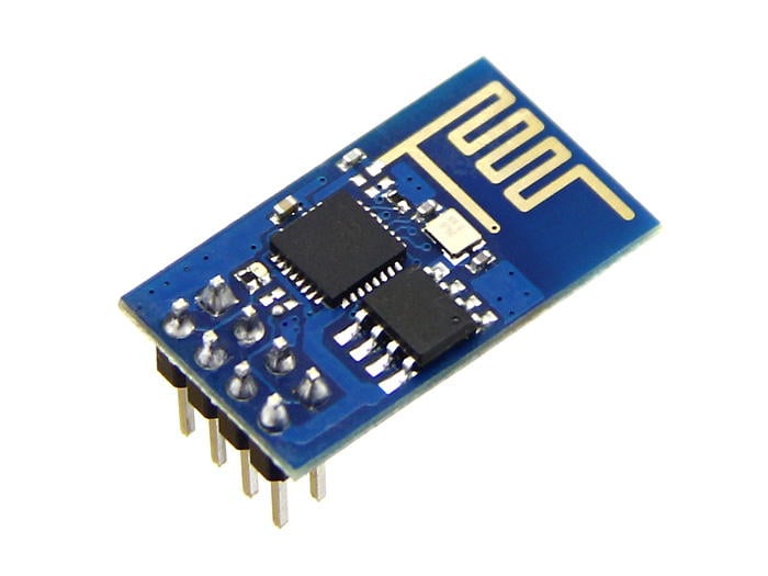
- ESP-01 comes with 8 pins (2 GPIO pins) – PCB trace antenna. (shown in above figure)
- ESP-02 comes with 8 pins, (3 GPIO pins) – U-FL antenna connector.
- ESP-03 comes with 14 pins, (7 GPIO pins) – Ceramic antenna.
- ESP-04 comes with 14 pins, (7 GPIO pins) – No ant.
etc.
For example, below figure shows ESP-01 module pins
ESP8266-01 Module Pinout and Description
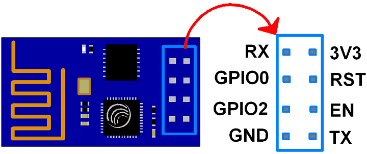
3V3: - 3.3 V Power Pin.
GND: - Ground Pin.
RST: - Active Low Reset Pin.
EN: - Active High Enable Pin.
TX: - Serial Transmit Pin of UART.
RX: - Serial Receive Pin of UART.
GPIO0 & GPIO2: - General Purpose I/O Pins. These pins decide what mode (boot or normal) the module starts up in. It also decides whether the TX/RX pins are used for Programming the module or for serial I/O purpose.
To program the module using UART, Connect GPIO0 to ground and GPIO2 to VCC or leave it open. To use UART for normal Serial I/O leave both the pins open (neither VCC nor Ground).
For more information refer http://esp8266.net/
Now, before we start with ESP8266 interfacing, we need to update its firmware.
Downloading Firmware’s
There are many software & hardware platforms, firmware’s and frameworks available, that are specific to their applications such as,
etc.
ESP8266 Firmware has been provided in binary format files (.BIN) that can be downloaded directly on the ESP8266 chip.
These binaries are generated using ESP8266 SDK (Software Development Kit), which is an application development platform produced by Espressif. Linux OS is required to compile the ESP8266 SDK. Windows user can use virtual machine.
For more information about ESP8266 SDK compilation refer -
ESP8266_Getting_Started_Guide or download below attached ESP8266 Getting Started Guide
After compilation, download firmware directly on ESP8266 chip over serial port.
Let’s download Espressif NON-OS SDK Firmware in to the ESP8266 module.
First download ESP8266 FLASH DOWNLOAD TOOL which is the official firmware download tool developed by Espressif.
Second download Espressif NON-OS SDK Firmware
Now select .bin files with their respective address as shown in below figure.
boot_v1.2.bin ------------------------------------------------> 0x00000
user1.1024.new.2.bin ------------------------------------------------> 0x01000
esp_init_data_default.bin ------------------------------------------------> 0xfc000
blank.bin ------------------------------------------------> 0x7e000
blank.bin ------------------------------------------------> 0xfe000
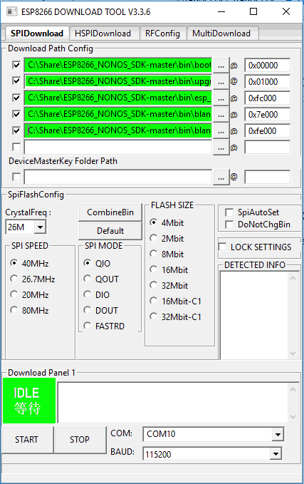
Note that, all binary (.BIN) files are available at ESP8266_NONOS_SDK-master\bin directory except user1.1024.new.2.bin which we can generate from SDK compilation and can be found in subfolder of ESP8266_NONOS_SDK-master\bin directory.
Ensure that you have selected the correct COM port and BAUD rate (115200 default).
Now let’s connect ESP8266 module to computer with RS232 standard serial port (using USB to Serial converter in case of laptop) as shown in below figure.
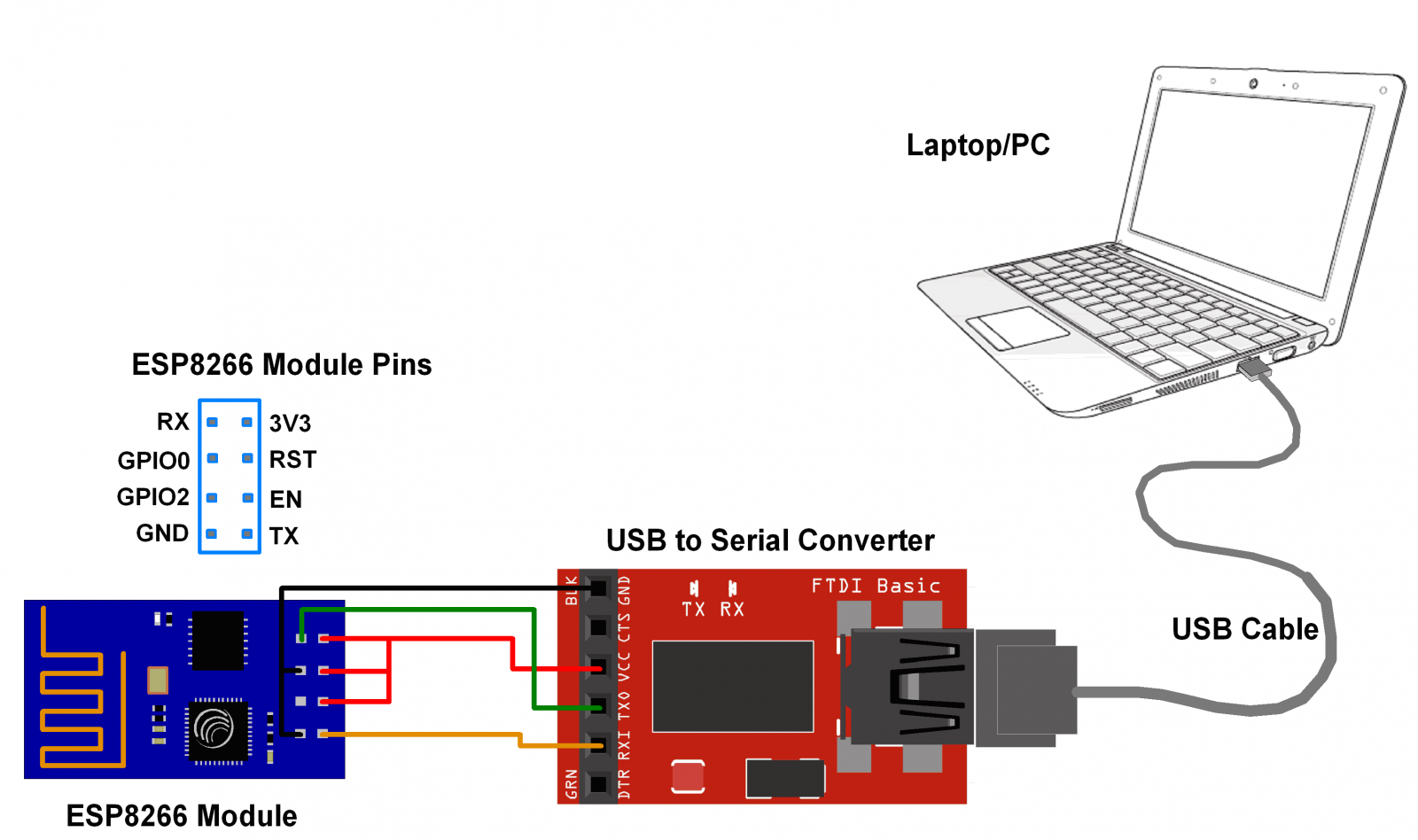
Note that, to put ESP8266 in flash mode, make connections as per above figure (in between ESP8266 and USB to Serial converter) and then only connect it to PC/laptop. Do not forget to connect GPIO0 pin to ground.
Then click on START tab in ESP8266 DOWNLOAD TOOL, and wait till it finishes. After finishing flash process, disconnect ESP8266 module from PC/laptop and remove ground connection at GPIO0 pin.
After successful downloading of firmware, we can use below AT commands for server and client communication using ESP8266.
Note: This time do not connect GPIO0 and GPIO2 pins (leave the open/unconnected).
ESP8266 AT Command Set
| Function | AT Commands | Response |
|---|---|---|
| Working | AT | OK |
| Restart | AT+RST | OK ....... Ready |
| Firmware Version | AT+GMR | <AT version info> information about AT version <SDK version info> information about SDK version <compile time> time of the bin was compiled OK |
| List Access Point | AT+CWLAP | +CWLAP:<ecn>,<ssid>,<rssi>,<mac>,<ch>,<freq offset> OK |
| Query Joined Access Point | AT+CWJAP? | +CWJAP:<ssid>,<bssid>,<channel>,<rssi> OK |
| Join Access Point | AT+CWJAP=”SSID”,”Password” | WIFI CONNECTED WIFI GOT IP OK |
| Quit Access Point | AT+CWQAP | OK WIFI DISCONNECTED |
| Get IP Address | AT+CIFSR (Assuming AT+CWMODE=3) | +CIFSR:APIP,<IP address> +CIFSR:APMAC,<mac address> +CIFSR:STAIP,<IP address> +CIFSR:STAMAC,<mac address> OK |
| Query WiFi Mode | AT+CWMODE? | +CWMODE:<mode> |
| Set WiFi Mode | AT+CWMODE=<mode> Mode: - 1 = STA (station) 2 = AP (Access Point) 3 = BOTH i.e. STA & AP | OK |
| Query TCP/UDP Connection | AT+CIPMUX? | +CIPMUX:<mode> |
| Set TCP/UDP Connection | AT+CIPMUX=<mode> Mode: - 0 = Single Connection 1 = Multiple Connection | OK |
| TCP/IP Connection status | AT+CIPSTATUS | STATUS:<status> Possible statuses are 2: Got IP 3: Connected 4: Disconnected |
| Query TCP transmission mode | AT+CIPMODE? | +CIPMODE:<mode> |
| Set TCP transmission mode | AT+CIPMODE=<mode> Mode: - 0 = Normal mode 1 = Transparent mode | OK |
| Set up TCP/UDP connection | (CIPMUX=0) AT+CIPSTART = <type>,<addr>,<port> (CIPMUX=1) AT+CIPSTART= <id>,<type>,<addr>, <port> Example (CIPMUX=0): AT+CIPSTART="TCP","192.168.101.110",80 | CONNECT OK |
| Send Data | (CIPMUX=0) AT+CIPSEND=<data length> (CIPMUX=1) AT+CIPSEND=<id>,<data length> | OK > (Note: write your data after > and enter it to send it will return status like.) Recv <data length> bytes SEND OK (after we receive response from server if any for default auto receive mode) (CIPMUX=0): + IPD, <length>: <data> (CIPMUX=1): + IPD, <id>, <length>: <data> |
| Close TCP/UDP Connection | AT+CIPCLOSE | CLOSED OK |
Examples of ESP8266 WiFi module Interfacing
Components Used |
||
|---|---|---|
| ESP8266 WiFi Module ESP8266 is a system on chip (SoC) which provides WIFI capability for embedded applications. This enables internet connectivity to embedded applications. ESP8266 modules are mostly used in Internet of Things(IoT) applications. |
X 1 | |