
- Basically in this project, coding is one of the most important thing, not understanding. DS1307 is a real-time clock IC. if you want to learn in detail then click on this link https://www.electronicwings.com/sensors-modules/real-time-clock-rtc-ds1307-module
- DS1307 is an I2C based IC and 8051 has no Inbuilt I2C protocol but show the below my code includes the header I2C file it's perfectly work in all 8051 MCU.
- Next thing is that we use the 128 x 64 graphical liquid crystal display to print the real-time and date from the RTC.
- Now if you want to learn more about the 128*64 GLCD then again search the electronicwings it gives a better understanding.
Diagram:
1. GLCD with 8051
.png)
2. DS1307 with 8051
.png)
Coding:
#include<reg51.h>
#include<delay.h>
#include<INTRINS.h>
#include<I2C.h>
sbit RS=P3^0;
sbit RW=P3^1;
sbit E=P3^2;
sbit CS1=P3^3;
sbit CS2=P3^4;
sbit RST=P3^5;
#include<E:/My DATA/8051/character.h>
#include<E:/My DATA/8051/character_num.h>
unsigned char sec,min,hr,day,date,month,year;
void init_rtc(void);
void rtc_read(void);
void bcd_to_hex(unsigned char y,unsigned char z,unsigned char x);
void convert_week_day(unsigned char x);
void main()
{
	init_rtc();
	glcd_init();
	glcd_string(67,0,"  REAL TIME CLOCK");
	glcd_string(67,3,"TIME:");
	glcd_string(67,5,"DATE:");
	while(1)
	{
		rtc_read();
		delay(500);

	}
}
void init_rtc(void)
{
	start();
	write(0xD0);   // Address of the DS1307
	write(0x00);
	write(0x51);   // sec starting from the 25
	write(0x59);   // MINUTES
	write(0x23);   // 12 hr mode
	write(0x02);   // Day - tuesday
	write(0x07);   // Date - 07
	write(0x07);   // Month- 07
	write(0x20);    // year - 2020
	stop();
}
void rtc_read(void)
{
	start();
	write(0xD0);
	write(0x00);   // address of the second reg

	start();  //restart
	write(0xD1);   // reading address of the reg
	sec=read();
	sec=sec & 0x7F;
	ack();
	min=read();
	min=min & 0x7F;
	ack();
	hr=read();
	hr=hr & 0x3F;
	ack();
	day=read();
	day=day & 0x07;
	day=day | 0x30;
	ack();
	date=read();
	date=date & 0x3F;
	ack();
	month=read();
	month=month & 0x1F;
	ack();
	year=read();
	year=year & 0xFF;
	nack();
	stop();
	CS2=1;
	CS1=0;
	bcd_to_hex(0x40,0xBB,hr);
	character(':');
	bcd_to_hex(0x51,0xBB,min);
	character(':');
	bcd_to_hex(0x61,0xBB,sec);
	bcd_to_hex(0x40,0xBD,date);
	character('/');
	bcd_to_hex(0x51,0xBD,month);
	character('/');
	bcd_to_hex(0x61,0xBD,year);
	convert_week_day(day);
}
void bcd_to_hex(unsigned char y,unsigned char z,unsigned char x)
{
	unsigned char xh,xl;
	xh=x & 0xF0;
	xh=xh>>4;
	xh=xh | 0x30;

	// Now convert the lower nibble into hex
	xl=x & 0x0F;
	xl=xl | 0x30;
	glcdcommand(y);
	glcdcommand(z);
	number(xh);
	number(xl);
}
void convert_week_day(char x)
{
	switch(x)
	{
		case '0' : {
			glcd_string(67,7,"      SUN");
			break;
		}
		case '1' : {
			glcd_string(67,7,"      MON");
			break;
		}
		case '2' : {
			glcd_string(67,7,"      TUE");
			break;
		}
		case '3' : {
			glcd_string(67,7,"      WED");
			break;
		}
		case '4' : {
			glcd_string(67,7,"      THU");
			break;
		}
		case '5' : {
			glcd_string(67,7,"      FRI");
			break;
		}
		case '6' : {
			glcd_string(67,7,"      SAT");
			break;
	}
}
}
- Firstly include all the header files, you already know DS1307 is the I2C compatible IC. then start writing the code. The writing address of the DS1307 is 0xD0.
- The address memory map is shown below.
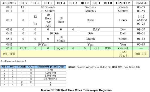
- Now add the data of the Time and date sequence. First write the data of sec, min, and Hr. Here hour is two types 12Hr mode and 24Hr mode so we basically use the 24Hr mode. then write the data of date, month, year and week_day. After writing all data put the stop condition.
- Now our goal to read the data from DS1307.
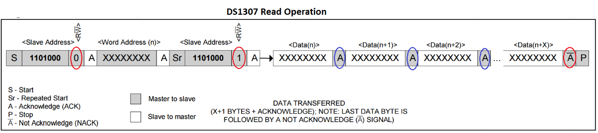
- Show the DS1307 read operation, one more thing when we read data from the DS1307 it's BCD format so we have to convert it into character (hex) Format.
- First, write the start condition then write the 0xD0 address of the DS1307 which means that read the data from this address and then again restart and write the reading address of the DS1307 (0xD1) and start the reading data from DS1307 it gives the data in sequences.
- Now convert the data character format.
- if the data is 0x25 BCD format then,
0x25 & 0x7F = 0x25
then mask the upper nibble
0x25 & 0xF0 =0x20 // ans is 0x20
0x20>>4 = 0x02; // then right shift in 4 bit
0x02 | 0x30= 0x32 // Oring operation with 0x30
Now show the ASCII table 0x32 mean character format is ' 2 '
now again mask the lower nibble
0x25 & 0x0F=0x05
0x05 | 0x30 = 0x35
Now show the ASCII table 0x35 mean character format is ' 5 '
- Then finally give this data to the Graphical display library it automatically print the data on GLCD.
- In this section, don't cover the Graphical LCD because the Electronicswings site give a better understanding.
#include<E:/My DATA/8051/character.h>
#include<E:/My DATA/8051/character_num.h>- Here I will write E:/My DATA/8051/character.h mean my library in a different folder so but you can put the same folder where your main.c file.
- This is the library file for the Graphical LCD. character.h for the print the character and number for the print the number.
- One most important things you have to give the most of the focus on the address of the GLCD.
- Now finally upload the code and show the result in Proteous as well as Hardware part.
Video