
Overview
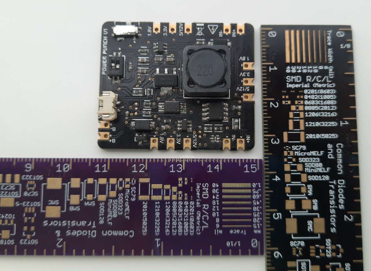
This is a petite integrated lithium-ion battery manager with Over Charge, Over Discharge, and Short Circuit protection.
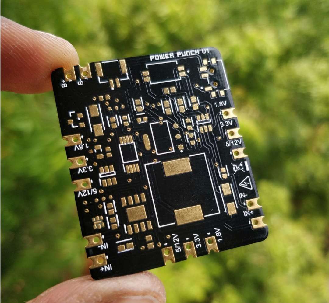
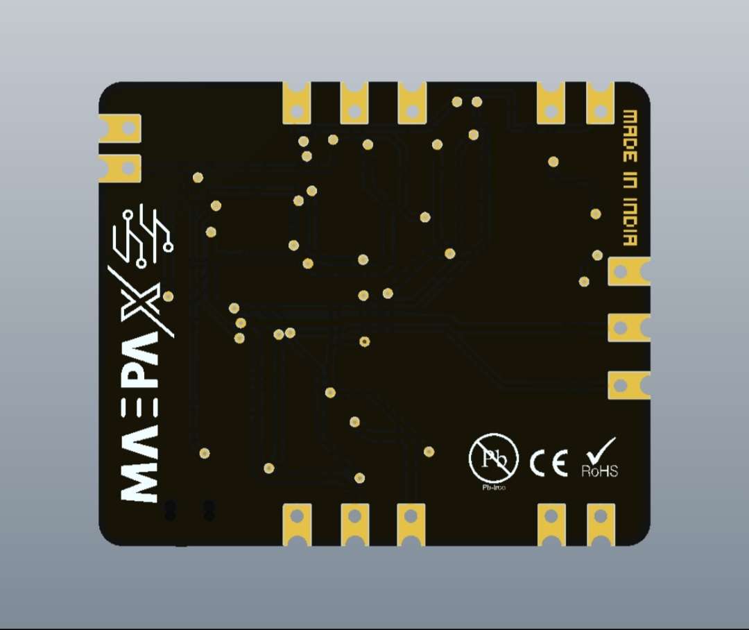
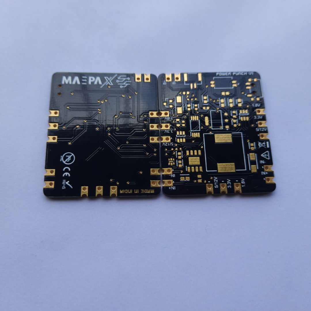
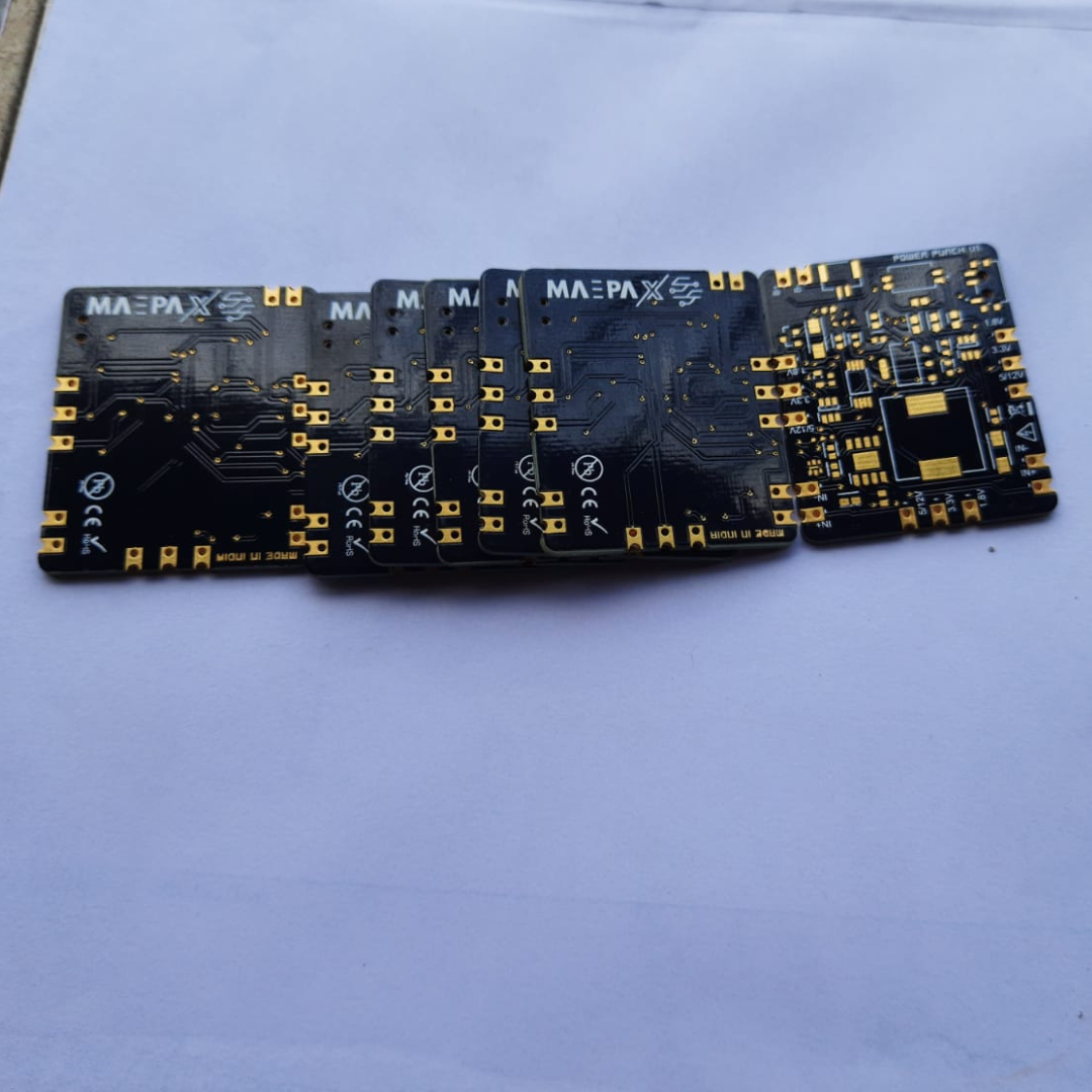
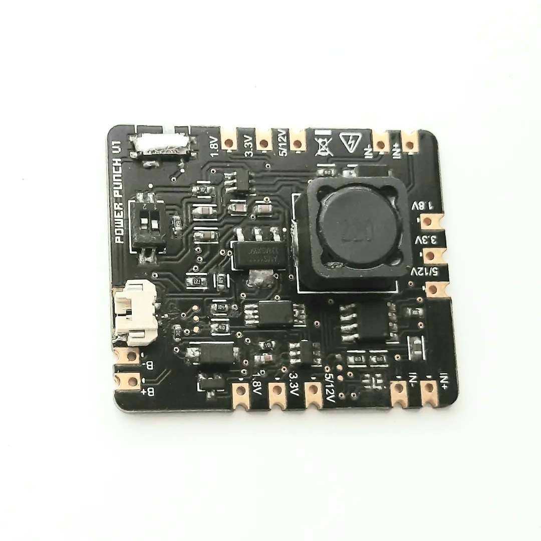
The board is designed in compact dimensions and aesthetic look of the Black Soldermask + ENIG Surface finish variant.
The Design!
This project is designed using 100% SMD components to make the board compact and small, so that it fits all types of enclosures and project need.
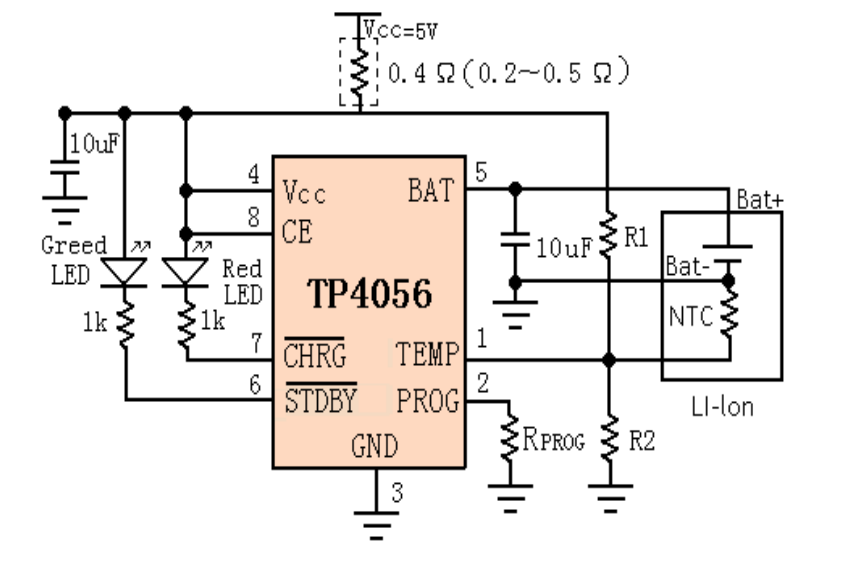
This board uses 3 main management or integrated chips i.e. TP4056, MT3608L and DW01. The purpose for each of this is simple.
- The TP4056 charges and discharges the 1S Battery.
- The MT3608L helps in boosting of the voltages upto 12V (in this board) and current upto 2.5A
- The DW01 manages the protection for the battery.
The Schematics!
- For the TP4056, we referred to the application schematic and simply followed it with some changes in the programmable resistors. Copying this schematic with the desired changes, the next part is the MT3608L.
2. For the MT3608L Boost converter, We used the output voltage formula to decide multiple output voltages by changing few reistors.
The formula we used is as follows:
.png) Here Vref is 0.6V and R1, R2 is the resistor value to get the Vout.
Here Vref is 0.6V and R1, R2 is the resistor value to get the Vout.
After designing the schematic, the next part is using the protection feature in our circuit.
.png)
3.
Why did we design it?
Designed by MakerPals and SciFi_Labs
We as a maker frequently work with multiple voltages and we all love the popular Lithium-Ion Cells/Batteries. We work with Microcontrollers (Eg: ESP MCUs) that work on 3.3v and some popular development boards like Raspberry Pi Pico, Arduino UNO, Arduino Nano, etc. Some discrete projects need 1.8V and some projects need 12V as the power supply.
We face the challenge of varying the voltage and sometimes we consider alternate boards for alternate voltages. A popular boost module on MT3608 acts friendly for us but it uses a potentiometer to vary the voltage, then we have to hot glue the pot and use it with a fixed voltage.
To solve this dilemma, We thought of modifying the electronics and making them precise with the popular voltage outputs only. We decided to use the most modern tech on this project with core components.
How did we start?
Our work started in March 2022, We browsed the web for all the information. Researched multiple MCUs, Maker problems, and datasheets. Finally, we were able to get a good design with the most common setup because most of the ICs were not available in the market and if it was, the cost couldn't be challenged.
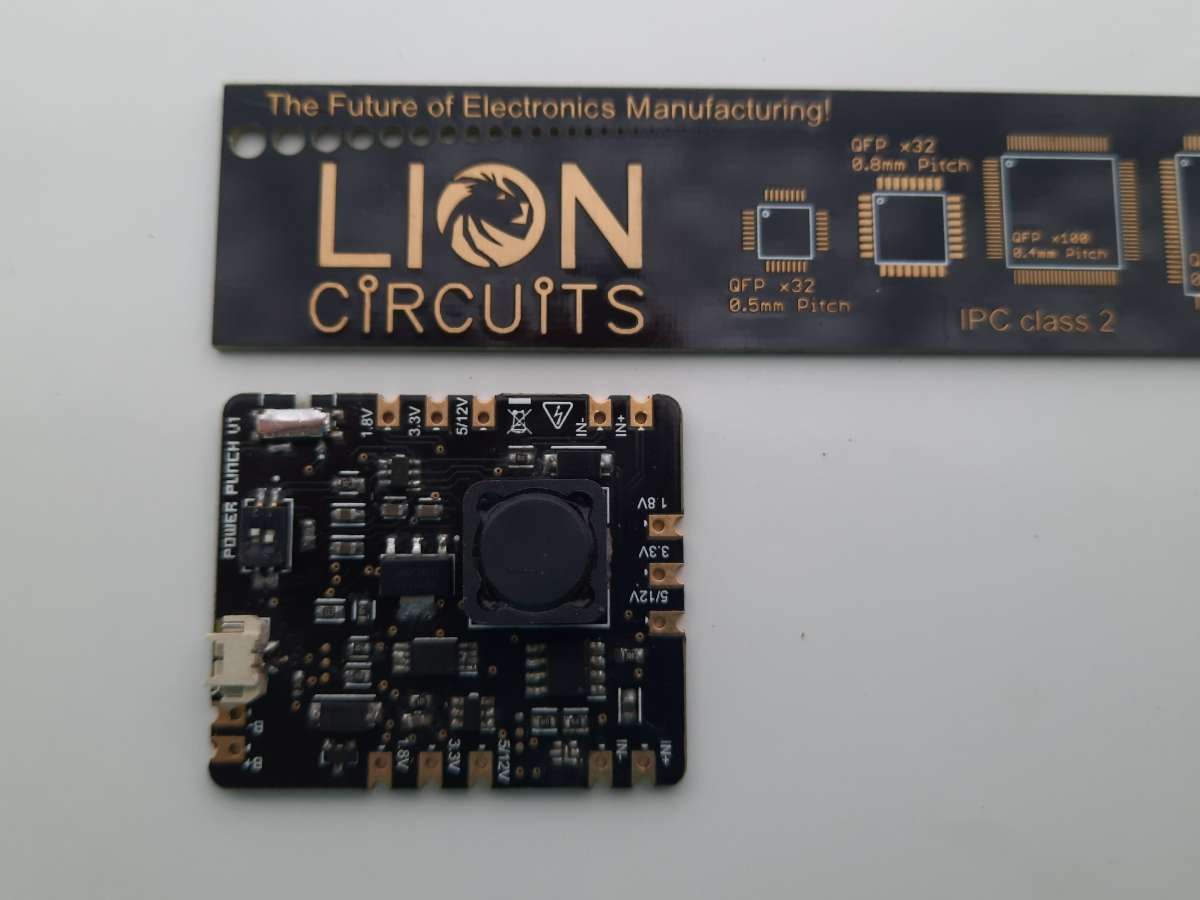
Moving towards PCB Design, we used the popular Altium Designer and Lion Circuits for PCB Fabrication.
PCB Quality and Feeback
We love giving the credits to all those who helped us in this project or in some way contribute to this build.
Lion Circuits - A trusted Indian PCB Manufacturer was able to help us once again with the PCB challenge.
The PCBs were fabrication in Black Soldermask with ENIG Surface Finish. The pricing was decent for 20 pieces at $80 with Shipping.
The quality of the board is absolutely rich following all the ISO standards.
We recommend choosing Lion Circuits for your PCB projects.
Features
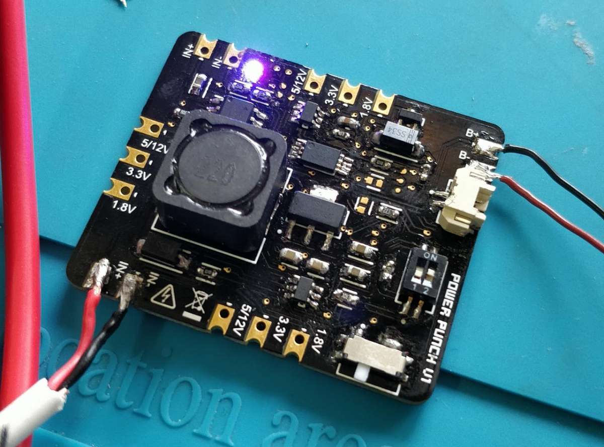
- Multiple Voltage Output gives the user, the freedom to power multiple components.
- Over Battery Charge, Over Battery Discharge, and Short Circuit Protection to the electronics.
- Completely Hand Soldered here in India
- 2.5A of Output current
- Battery (LGDAS31865) Charging time of 2hrs and Discharge times of 3.5hrs for 12V 0.2A load.
- Multiple LED Indication for Battery charging, discharging, and 3.3V modes.
- Switch between 5v and 12v
- JST Connector for Li-Po Batteries
How can you get it?
You can order either the PCB or the complete product from this store: www.tindie.com/stores/maepa
We hope that you would love this offering. We encourage you to get this board and use it in your projects.
Till then, have a happy build.
Namaste!