...continued from part 1
This section continues the MotorMindAI v1 project. For a complete understanding of the system design, hardware setup, and software implementation, it is recommended to review Part 1 before proceeding.
To Refer Part 1 Click this: MotorMindAI v1 Part 1
RETRY MECHANISM:
if (millis() - lastWifiCheck > wifiRetryInterval)This ensures:
- Stable reconnection.
- No blocking delays.
Insights: " The integration of Blynk IoT enables real-time remote monitoring and intelligent alerting, making the system suitable for smart industrial environments. Combined with Edge AI, the system achieves both local intelligence and global accessibility."
7.2.11 LOGGER MODULE: "logger.h"
OVERVIEW:
The file logger.h manages serial logging for debugging, monitoring, and dataset collection. It provides multiple logging modes that help in system development, testing, and machine learning data generation.
PURPOSE:
- Debug system behaviour
- Monitor real-time performance
- Generate a dataset for ML training
- Switch logging modes dynamically
7.2.11.1 LOGGING MODES: (system supports three logging modes)
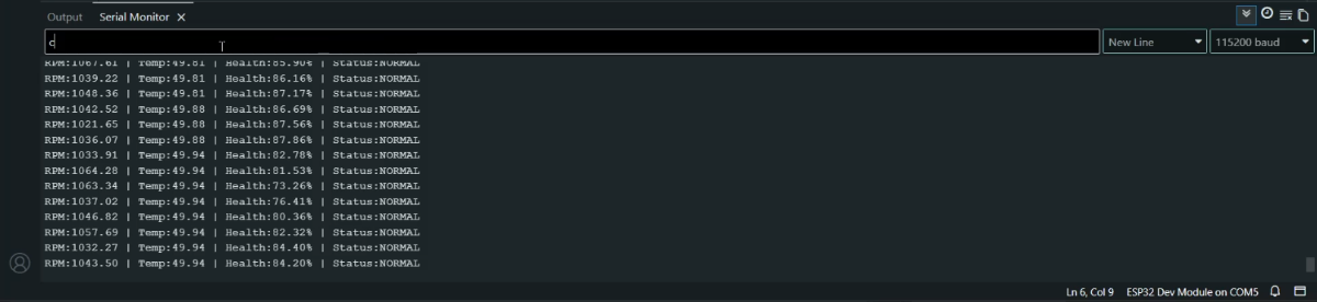
d → DEBUG mode
i → INFO mode
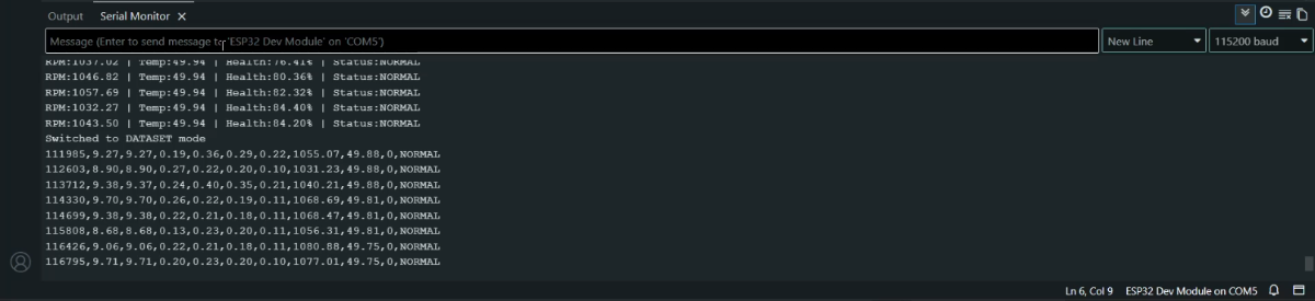
c → DATASET mode 7.2.11.2 MODE SWITCHING (SERIAL CONTROL)
char cmd = Serial.read();if(cmd == 'd') logMode = LOG_DEBUG;
else if(cmd == 'i') logMode = LOG_INFO;
else if(cmd == 'c') logMode = LOG_DATASET;Allows real-time switching without reprogramming.
7.2.11.3 DEBUG MODE (Used for system troubleshooting)
logDebug(...)- Displays all sensor values
- Shows AI prediction
- Displays motor health and fault
7.2.11.4 INFO MODE (Used for quick monitoring)
logInfo(...)OUTPUT FORMAT:
RPM:1450 | Temp:36 | Health:85% | Status:NORMAL7.2.12.5 DATASET MODE(Directly generates data for ML Training)
logDataset(...)OUTPUT FORMAT (CSV):
time,vibRMS,vibMean,vibStd,currentRMS,...,prediction,fault7.2.12.6 MAIN LOGGER: ( Automatically selects logging behaviour)
runLogger(...)Insights: " The logger module enables efficient debugging, real-time monitoring, and direct dataset generation for machine learning. Its multi-mode design allows seamless transition between development and deployment phases, making the system both practical and scalable."
7.3 ARDUINO LCD INTERFACE CODE STRUCTURE: "Arduino_LCD_Animation.ino"
OVERVIEW:
This file manages the LCD using the Arduino, providing a dedicated interface for system visualisation and startup feedback. It initialises the LCD, displays a startup animation sequence, and later shows real-time motor status received from the ESP32 via UART communication.
MAIN FUNCTIONS USED:
lcd.init()           -> Initializes the LCD module
lcd.backlight()      -> Enables LCD backlight
lcd.setCursor()      -> Positions cursor for display
lcd.print()          -> Displays text on LCD
delay()              -> Creates animation timing
SoftwareSerial()     -> Enables UART communication with ESP32
Insight: " This design follows a modular architecture where display handling is separated from the main processing unit. By delegating LCD control to the Arduino, the ESP32 avoids unnecessary overhead and maintains consistent real-time performance for Edge AI inference.
This approach improves system responsiveness, ensures smooth UI updates, and demonstrates effective multi-controller communication using UART."
8. RESULTS AND OBSERVATIONS
The MotorMind AI system was successfully tested under real-time operating conditions. The system continuously monitored vibration, current, temperature, and motor speed, and performed on-device inference using the embedded Decision Tree model.
The Blynk IoT dashboard provided real-time visualisation of sensor data through gauges and live graphs. The motor, operating under normal conditions, showed stable vibration (~8–9 g), current (~0.21–0.26 A), and temperature (~30°C), indicating healthy operation.
The system accurately classified motor states and displayed the corresponding health condition (NORMAL / WARNING / FAULT) on both the IoT dashboard and local displays (OLED & LCD). The response time was minimal due to Edge AI processing, ensuring instant detection and alert generation.
.jpeg) | 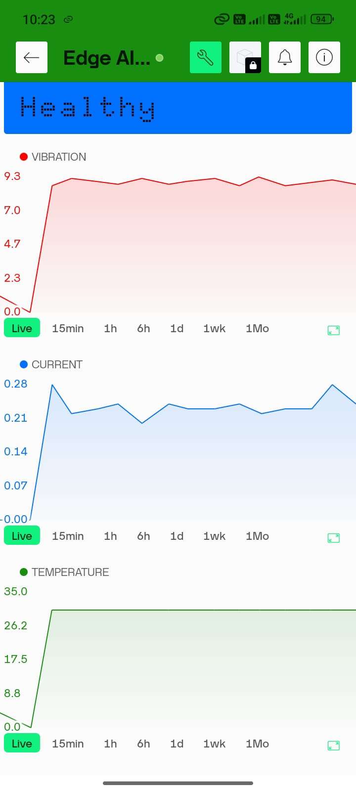 |
9. WHAT MAKES "MotorMindAI v1" UNIQUE:
MotorMind AI stands out by combining embedded systems with Edge AI to deliver a fully autonomous and intelligent motor monitoring solution.
Unlike traditional systems that rely on threshold-based detection or cloud processing, this system performs real-time fault classification directly on the ESP32 using a trained machine learning model. This eliminates latency, reduces dependency on internet connectivity, and ensures faster decision-making.
The system integrates multi-sensor data (vibration, current, temperature, and RPM) and applies feature extraction techniques such as RMS, mean, and standard deviation to improve prediction accuracy. Additionally, it includes a motor health estimation model with Remaining Useful Life (RUL) prediction, enabling predictive maintenance rather than reactive monitoring.
The modular firmware architecture, dual-controller design (ESP32 + Arduino), and built-in dataset logging capability further enhance scalability, reliability, and practical usability in real-world industrial environments.
10. PROJECT BUILD INSTRUCTIONS: STEP-BY-STEP
10.1: DEVELOPMENT ENVIRONMENT SETUP
STEP 1: Install and Open Arduino IDE
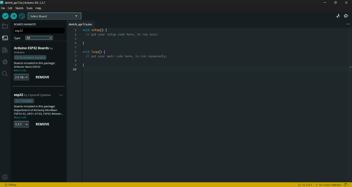
STEP 2: Install the ESP32 board package
- Preferences --> Add ESP32 board URL--> Copy and paste this URL -->
https://espressif.github.io/arduino-esp32/package_esp32_index.json
- (OR) Board Manager --> Find esp32 libraries --> Click "Install"
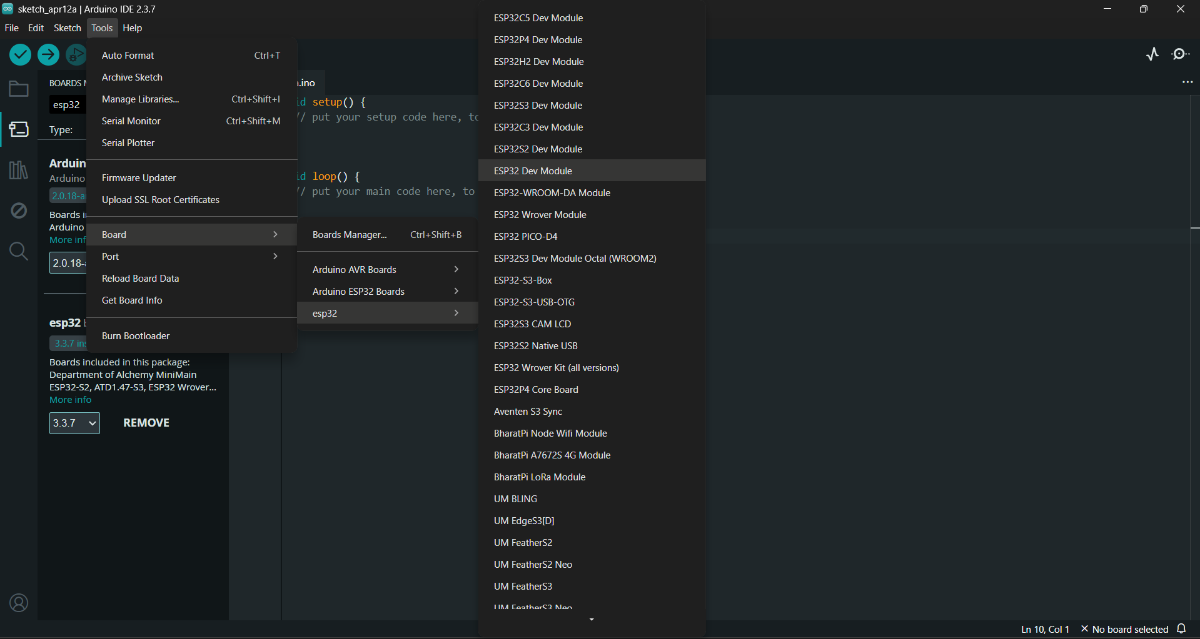
STEP 3: Select Board:
- Tools → Board → ESP32 Dev Module
- Tools --> Port --> choose serial port
STEP 4: Install these required libraries:
#include <Wire.h>
#include <Adafruit_Sensor.h>
#include <Adafruit_ADXL345_U.h>
#include <OneWire.h>
#include <DallasTemperature.h>
#include <Adafruit_GFX.h>
#include <Adafruit_SSD1306.h>
#include <WiFi.h>
#include <WiFiClient.h>
#include <BlynkSimpleEsp32.h>- Tools --> Manage Libraries
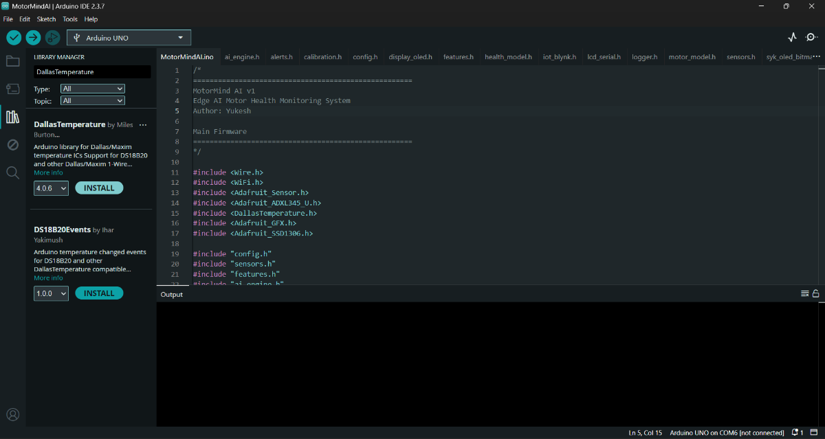
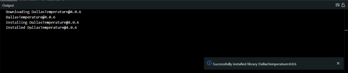
After installing all the Libraries, close the Arduino IDE.
STEP 5: Download and Install Python (Miniconda) Environment :
STEP 6: Open Anaconda Prompt.
STEP 7: Create a new environment: Paste this.
conda create -n motormind python=3.9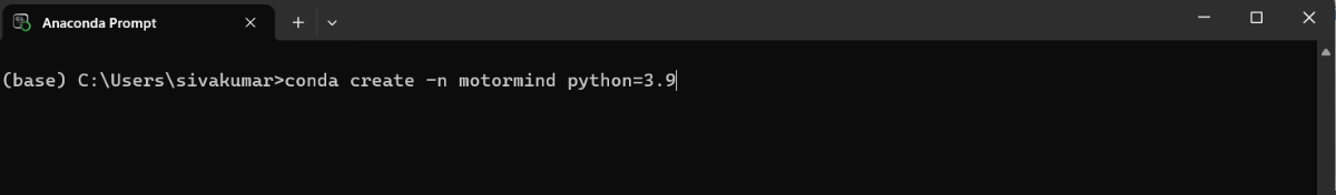
Press Enter.
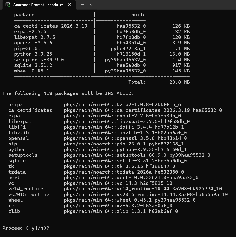
- Type "y" --> Press Enter
STEP 8: Activate the environment: Paste it and press Enter.
conda activate motormind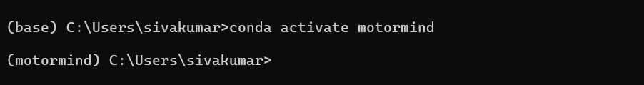
STEP 9: Install required libraries: Paste it and press Enter
pip install numpy pandas scikit-learn matplotlib joblib micromlgen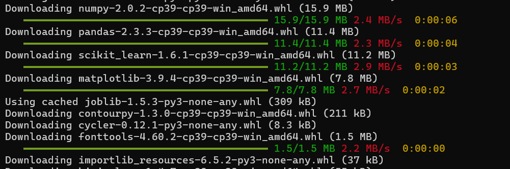
STEP 10: Navigate to the project folder: (project folder from GitHub repo)
cd path\to\Motor_ML_ProjectSTEP 11: Verify installation:
pythonThen type and Press Enter:
import numpy
import pandas
import sklearn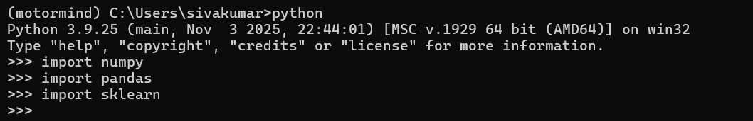
If no error, it means the setup is successful.
LIBRARIES INSTALLED:
numpy --> numerical operations
pandas --> dataset handling
scikit-learn --> Decision Tree model
matplotlib --> data visualization
joblib --> model saving/loading
micromlgen --> convert ML to Embedded deployment
CAUTIONS:
- Always activate environment before running training
- Do not install libraries in base environment
STEP 12: Download project source code from GitHub: "Click to view repo"
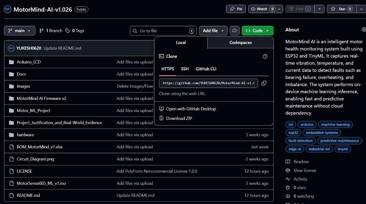
This project Source code is licensed under the PolyForm Noncommercial License 1.0.0.
You may use, modify, and share this project for non-commercial purposes only.
STEP 13: Extract project folder. <-----ENVIRONMENT SETUP DONE
10.2 HARDWARE PREPARATION
PRE-CHECK (REFER PART 1)
- Components list is already provided in Part 1 (Components Section)
- Pin configuration is already defined in Part 1(Pin Configuration Table on" 6.3")
- A BOM (.xlsx) file is attached in the downloads section at the end
---> Kindly refer to it for exact pricing and component purchase sources
STEP 14: Place the ESP32 and Arduino UNO on the breadboard area.
STEP 15: Provide a common GND connection between the ESP32 and the Arduino.
STEP 16: Connect power lines:
- ESP32 ---> USB (Laptop)
- Arduino ---> Battery source
STEP 17: Connect sensors based on the Part 1 pin table:
- ACS712 20A---> Analog pin
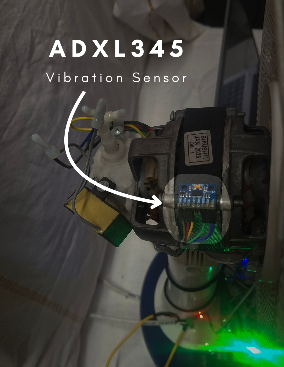
- ADXL345 ---> I2C (SDA, SCL)
- CS pin --> VCC and SD0 pin --> GND
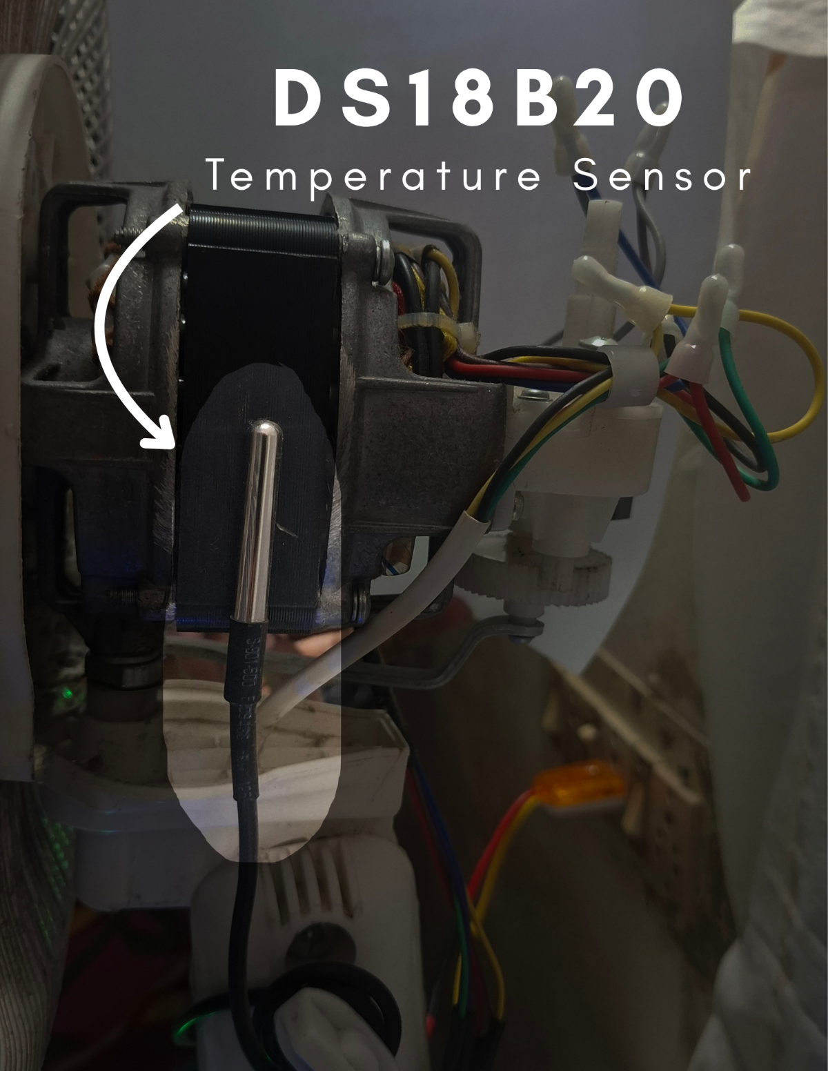
- DS18B20 ---> Digital pin (with pull-up resistor)
- IR sensor ---> Digital input
STEP 18: Connect output devices:
- LEDs ---> through resistors
- Buzzer ---> digital output
- OLED --> I2C
- LCD --> I2C Module --> Arduino UNO
ADXL345 and OLED both shared the same I2C bus. kindly refer section 6.3 on part1
STEP 19: Connect the 0.1uF capacitor near every sensor across VCCpin and GNDpin to remove high-frequency noise.
STEP 20: Connect a 10uF Capacitor across the current sensor's VCC pin and GND pin to smooth voltage fluctuations.
STEP 21: Connect the 4.7kOhm Resistor across the Data pin and the VCC pin
STEP 22: Connect the 220Ohm Resistor between led's Cathode pin and the GND to prevent damage.
STEP 22: Ensure all jumper wires are firmly connected and that proper power connections are made.
STEP 23: Make sure the circuit connections are made as per the circuit diagram below.
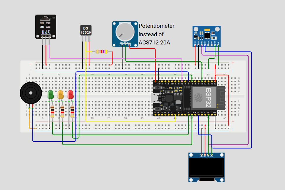 |  |
|---|---|
| Kindly refer to Figure 4.2, Figure 14, and Figure 15 in Part 1. | |
10.3 MOUNT SENSORS ON MOTOR:
MOTOR SELECTION AND SPECIFICATIONS: ( SINGLE PHASE INDUCTION TYPE )
PROTOTYPE MOTOR USED:
| 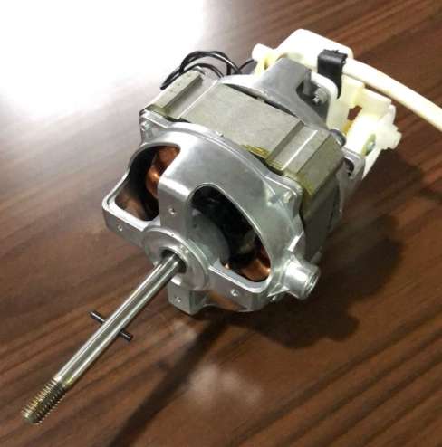 | For Additional Information, click this " Link " |
INDUSTRIAL MOTOR (SCALABLE MODEL):
| 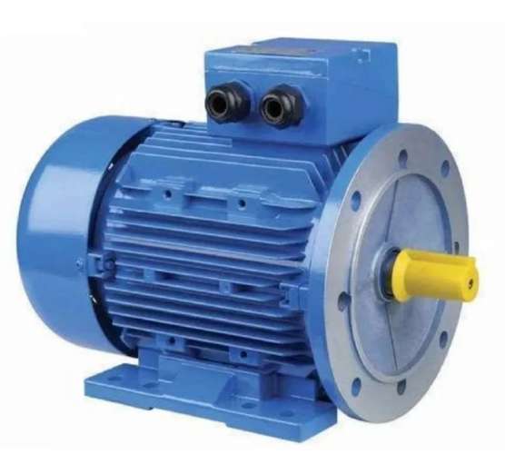 | For Additional Information, click this " Link " |
| This project is designed as a low-power prototype (55W) but can be directly scaled to industrial motors by upgrading sensing, protection, and isolation mechanisms while retaining the same Edge AI logic. | ||
STEP 24: Select a working motor for testing.
STEP 25: Ensure the motor is stable and properly mounted.
STEP 26: Connect the power supply safely.
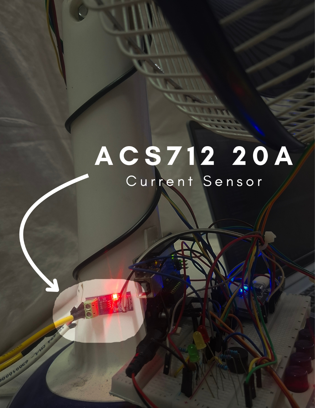
STEP 27: Place the DS18B20 close to the motor surface. Stick it with the glue. | STEP 28: Fix the ADXL345 (vibration sensor) firmly on the motor body. Stick it with the glue. | STEP 29: Align the IR sensor with the rotating blade and attach the reflective tape. Stick it with the glue. | STEP 30: Connect the ACS712 20A current sensor in series with the motor power line:
|
 |  | 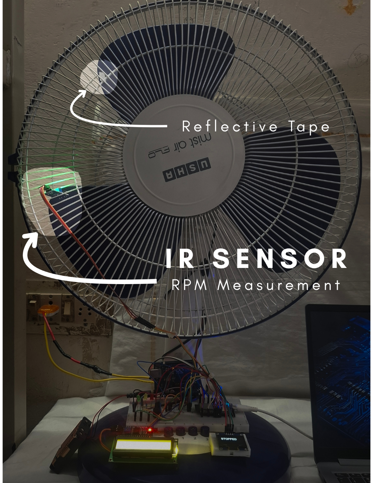 |  |
STEP 31: Adjust the trimmer on the IR sensor to set the threshold so it detects only the reflective tape and ignores the surrounding surface.
STEP 32: Ensure a tight screw connection on the ACS712 terminals.
STEP 33: Route all wires safely away from moving parts.
STEP 34: Ensure proper insulation of exposed wires.
STEP 35: Double-check polarity of capacitors.
ADDITIONAL STEPS REQUIRED FOR INDUSTRIAL IMPLEMENTATION:
STEP 36: Use Current Transformer (CT) instead of ACS712 20A.
STEP 37: Implement electrical isolation (opto-isolators).
STEP 38: Add proper grounding and shielding.
STEP 39: Use industrial-grade vibration mounting (bolted/epoxy).
STEP 40: Ensure secure temperature probe placement.
STEP 41: Add protective enclosure for electronics.
If you using the table fan motors, you may avoid these above steps.
CAUTIONS:
- Avoid short circuits on breadboard.
- Do NOT connect ACS712 in parallel (must be series).
MAKER NOTE:
- Sensor placement directly affects accuracy of ML predictions.
- Stable hardware = reliable sensor data = better ML accuracy
10.4 FIRMWARE SETUP (ESP32 + ARDUINO)
PRE-CHECK (REFER PART 1)
Firmware architecture and workflow are already explained in Section 7.2 on Part 1.
Kindly refer Part 1 for detailed understanding of firmware structure and logic.
10.4.1. FIRMWARE FOLDER STRUCTURE (FROM GITHUB REPOSITORY)
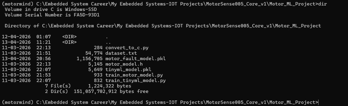
1.MotorMind AI Firmware v2
     |----> MotorMindAI.ino (Main control program)
     |----> Header files: ( .h )
2.Arduino_LCD
     |----> Arduino_LCD_Animation.ino
3.Motor_ML_Project
     |----> dataset.txt
     |----> .py , .pkl
     |----> motor_mind.h (Trained ML model)
10.4.2. ESP32 FIRMWARE UPLOAD:
STEP 42: Open Arduino IDE
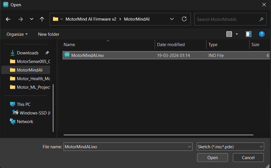
STEP 43: Open file: File --> Open... ---> Select "MotorMind.ino"
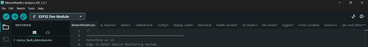
STEP 44: Add Header Files: Sketch --> Add File... --> Select .h files
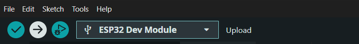
STEP 45: Select board: Tools --> Board --> ESP32 Dev Module
STEP 46: Select the correct COM port.
STEP 47: Click Upload
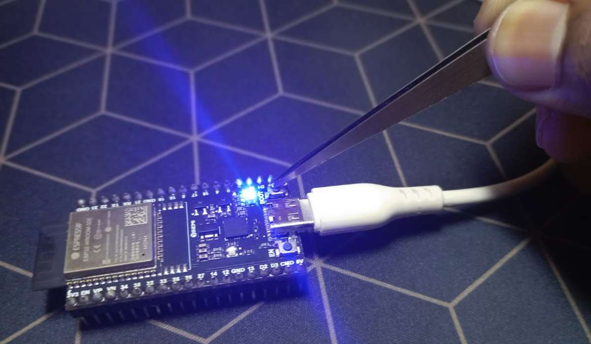
STEP 48: When “Connecting…...” appears:
- Press and hold the BOOT button on the ESP32
- Release after upload starts. (Some ESP32 boards require this for flashing)
STEP 49: Wait for the “Upload Successful” message.
10.4.3. ARDUINO FIRMWARE UPLOAD: (Same Procedure as above for ESP32)
STEP 50: Open a new tab for Arduino: File --> New Sketch
STEP 51: Again Click File ---> Open... ---> Select Arduino_LCD_Animation.ino
STEP 52: Select board: Tools --> Board --> ESP32 Dev Module
STEP 53: Select another COM port for the Arduino UNO Board.
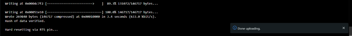
STEP 54: Click Upload and wait for the “Done Uploading” message.
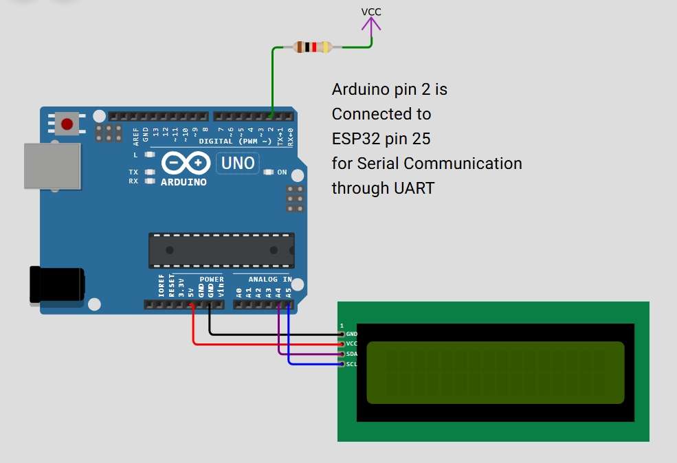
10.4.4. SERIAL COMMUNICATION CHECK:
STEP 55: Make a connection: ESP32 GPIO25 --> Arduino D2
STEP 56: Verify both boards are powered. (Better to power both from the same supply)
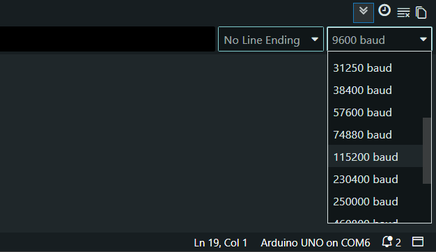
STEP 57: Open the Serial Monitor and set the serial monitor baud rate to 115200.
STEP 58: Ensure the same baud rate in both programs.
STEP 59: Power ON the system and observe: ( System initialization check )
- OLED display ---> system start
- LCD ---> status message
- LEDs ---> initial state
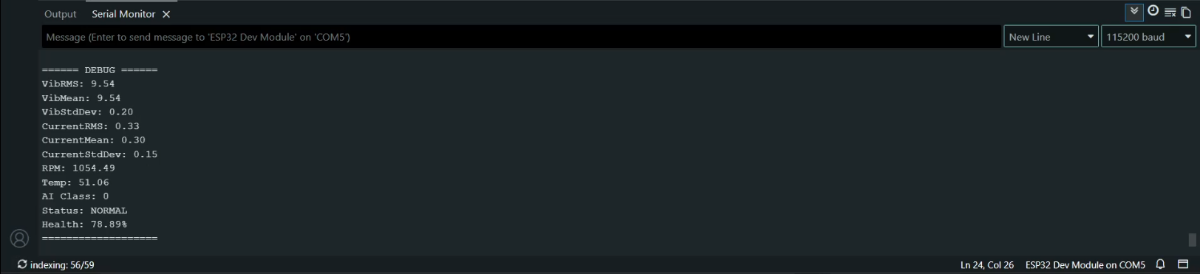
STEP 60: Open Serial Monitor on the ESP32 program (To Collect Dataset)
STEP 61: Send the command " c " so that the system enters Dataset Mode.
STEP 62: Run motor in different conditions:
- Normal
- Load variation (Slightly block the air flow through the blade on any one side )
- Unbalance ( Make the controlled vibration on the table fan near the motor )
- Overheat ( Allow it to run continuously for 4 hours in mid-afternoon )
STEP 63: Sensor data will stream via serial. Copy and paste (save) data into the dataset.txt file for different conditions. Collect a balanced dataset (all conditions).
| When the motor is stopped |  |
| At Normal condition | 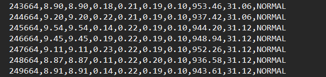 |
| At the load Variation condition | 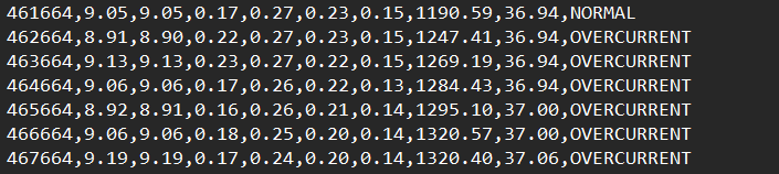 |
| At the Unbalanced condition | 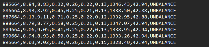 |
| At an overheated condition | 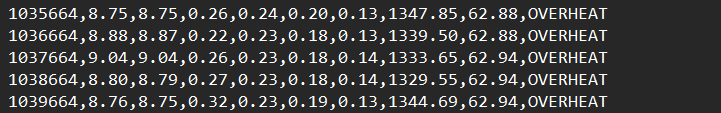 |
10.5 ML TRAINING & EDGE AI PREPARATION:
PRE-CHECK:
- Full firmware working is explained in Part 1 (Software & ML Implementation).
- Kindly refer Section 7.1 on Part 1 for internal working details.
- Dataset (dataset.h) must be collected from STEP 62
- Ensure that STEP 5 to STEP 13 are completed.
Thus, Anaconda Prompt was opened, and the environment was activated.
STEP 64: Navigate to the project folder: Copy the path to the "Motor_ML_Project" folder.
cd "Paste here" \Motor_ML_ProjectSTEP 65: Copy and paste the above line on the Anaconda prompt ---> Press Enter
STEP 66: Verify files present in the folder using the command " dir ".
STEP 67: Train the main model (random forest) by running this file.
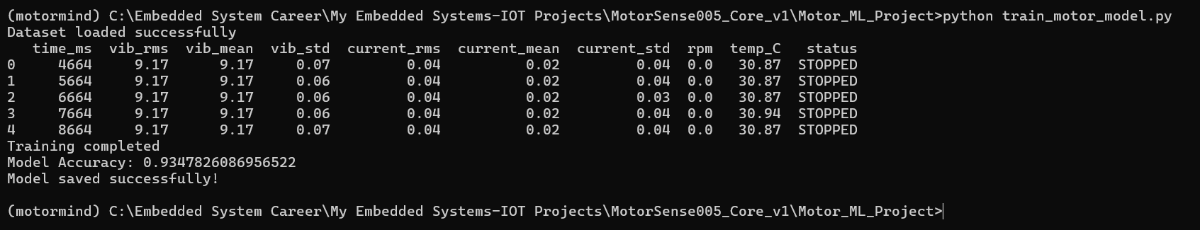
python train_motor_model.py Paste this and press Enter; It will generate a "motor_fault_model.pkl" file.
STEP 68: Train the EDGE AI Model (Decision Tree) by running this file.
python train_tinyml_model.pyPaste this and press Enter; It will generate the "tinyml_model.pkl" file.
.png)
NOTE: Decision Tree is used for ESP32 deployment (lightweight).
STEP 69: Run this file for model conversion ( .pkl ---> .h )
python convert_to_c.pyPaste this and press Enter; It will generate the "motor_model.h" file.

CAUTIONS:
- Do NOT rename files.
- Do not modify generated file.
- Run commands in correct order.
- Do not skip TinyML training (used for deployment).
STEP 70: Open Arduino IDE for EDGE AI DEPLOYMENT.
STEP 71: Open ESP32 firmware: "MotorMindAI.ino"
STEP 72: Sketch ---> Add File... ----> Select "motor_mind.h" ----> Click Open
STEP 73: Ensure model is included in code:
#include "motor_model.h"STEP 74: Click Upload and press the BOOT button when “Connecting…” appears
STEP 75: Verify the AI Predictions by observing real-time output on the Serial monitor.
MAKER NOTE: Inference runs fully on ESP32 (Edge AI -- no cloud required).
10.6 IOT SETUP (BLYNK)
PRE-CHECK (REFER PART 1)
- IoT logic and Blynk integration are explained in Part 1 (Section 7.2.10) & Part 2 (continued...). and Ensure firmware already includes Blynk configuration.
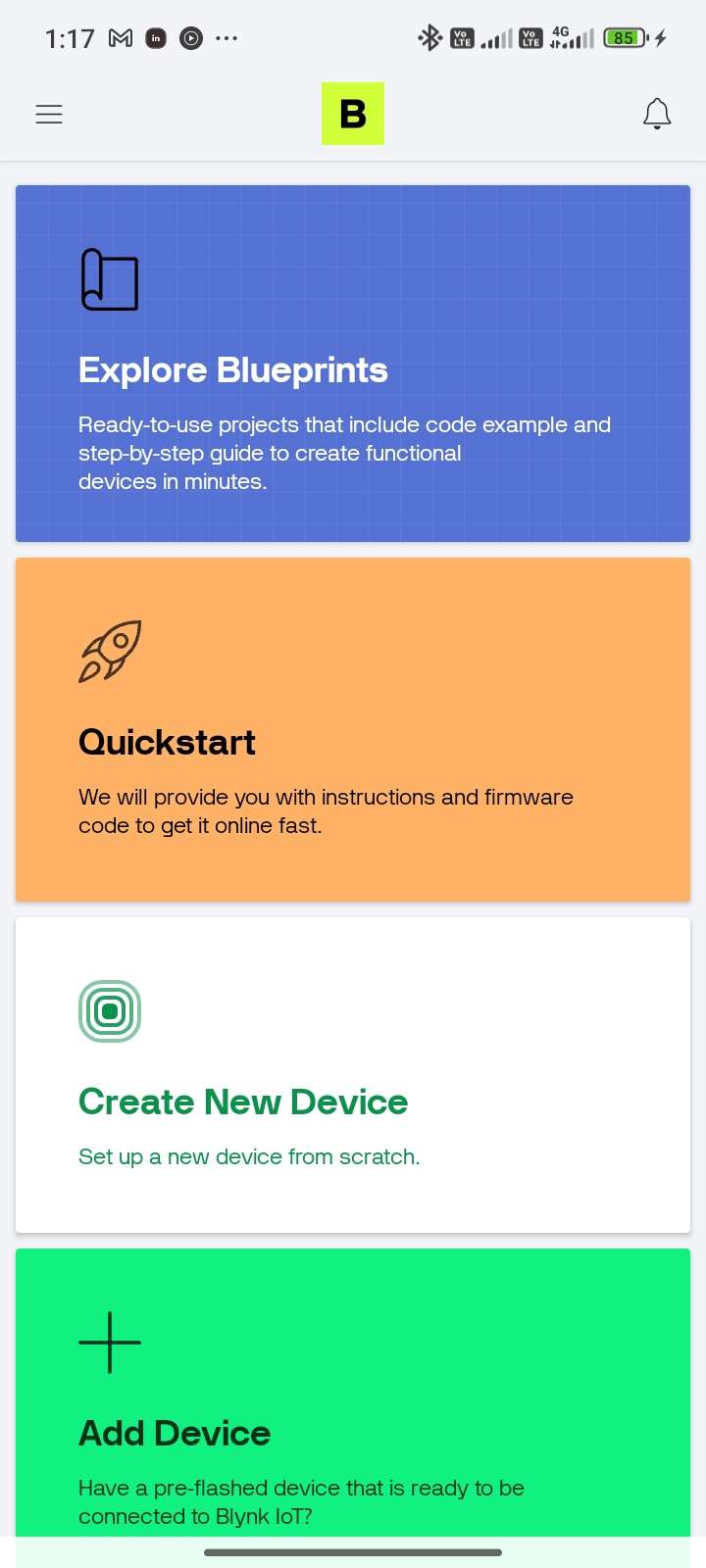
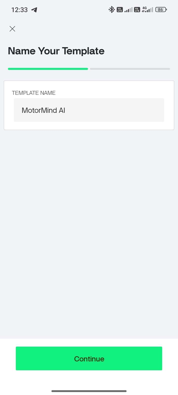
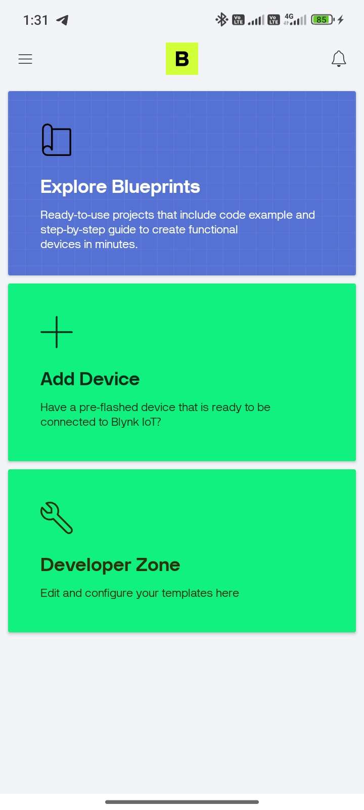
| STEP 76: Open Mobile Play Store / App Store --> Search: Blynk IoT --> Install application | ||||
| STEP 77: Open the app and Sign Up/Login | STEP 78: Tap “Create New Device” | STEP 79: Enter: Template Name and click Continue. | STEP 80: Come to the Main page and Select "Developer Zone" | STEP 81: Tap “MotorMind AI” template |
 |  |  |  | 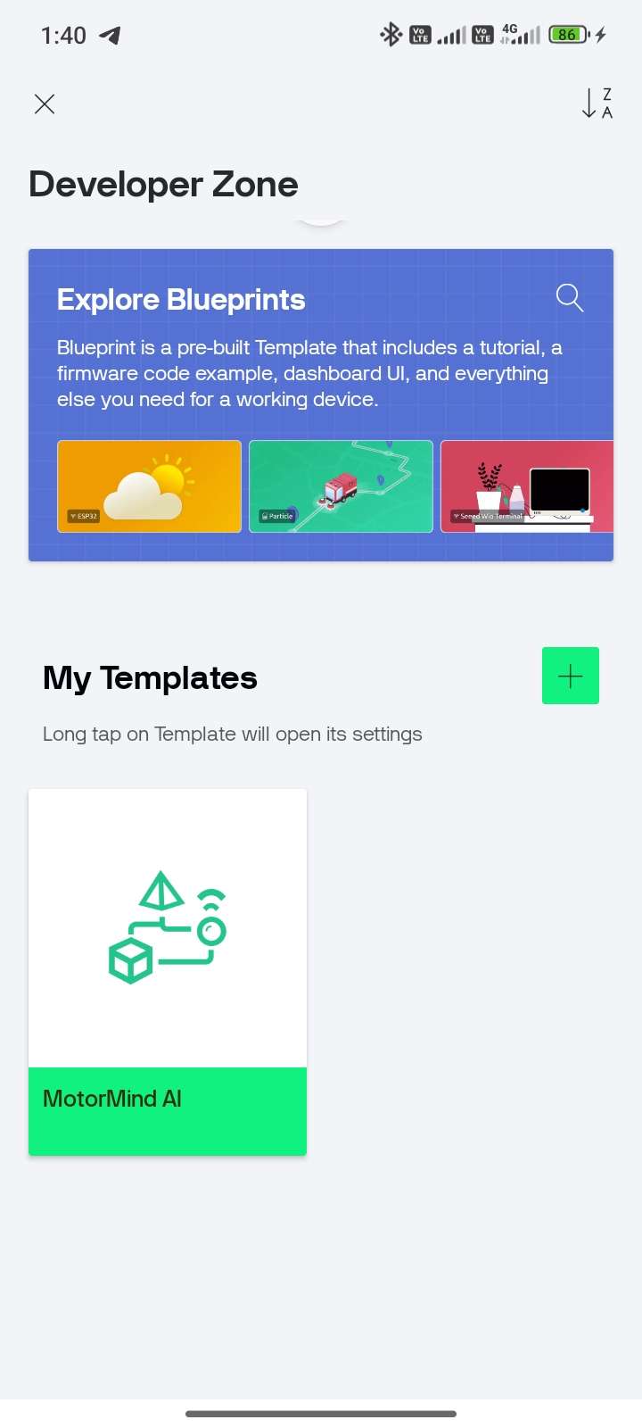 |
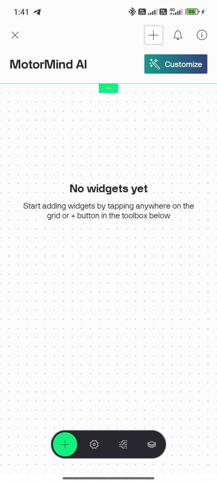
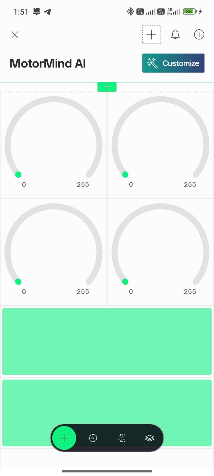
STEP 82: Tap “+” button and
| STEP 83: Add widgets (Gauge / LCD / Graph) | STEP 84: Select the Datastream icon near "+" and select the green bar. | STEP 85: Configure the Virtual Pin Datastream | STEP 89: V0 -- TEMPERATURE Select as mentioned below |
 |  | 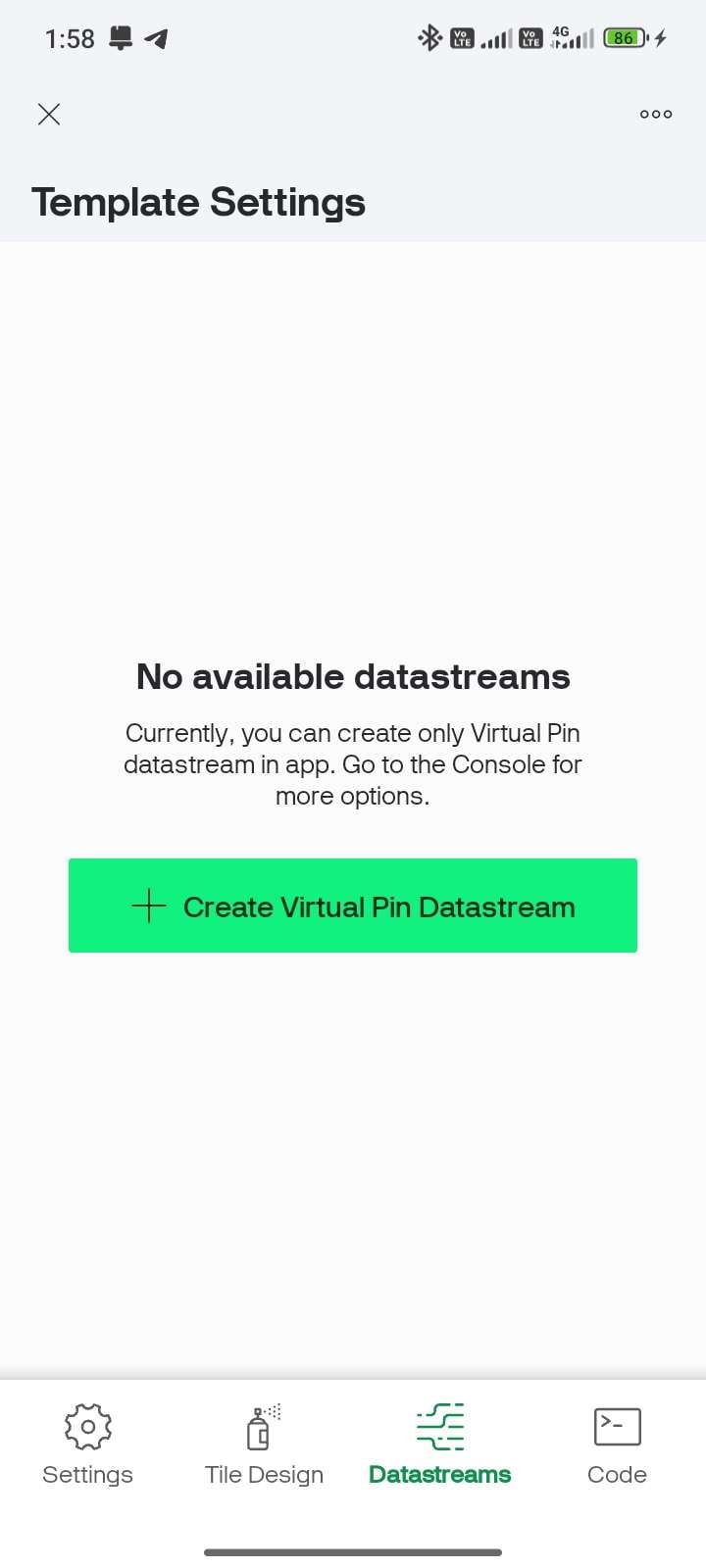 | 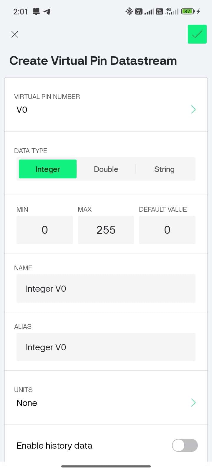 | Data Type -- Double Min -- 0 Max -- 100 Name -- Temperature Units -- `C |
| STEP 90: V1 -- VIBRATION | STEP 91: V2--CURRENT | STEP 92: V3 -- MOTOR HEALTH | STEP 93: V4 -- FAULT STATUS | STEP 94: V5 -- RPM |
Data Type Double Min -- 0 Max -- 10 Name Vibration Units -- Gram | Data Type -- Double Min -- 0 Max -- 0.4 Name -- Current Units -- A | Data Type -- Integer Min -- 0 Max -- 100 Name -- Motor Health Units -- % | Data Type -- String Name -- Fault Units -- None | Data Type -- Integer Min -- 0 Max -- 1500 Name -- RPM Units -- RPM |
| STEP 95: V6, V7, V8,and V9 | STEP 96: V10 - RUL(Remaining Useful Life) | STEP 97: V11-MAINTENANCE ALERT | STEP 98: Map the Virtual pin Datastreams to the widgets | STEP 99: Tap the Info icon at the top right corner, copy the AUTH TOKEN |
Data Type -- Integer Min -- 0 Max -- 1 Name -- Fault LED Change this for the specific LED , Buzzer | Data Type -- Integer Min -- 0 Max -- 100 Name -- RUL Units -- % | Data Type -- String Name -- Maintenance | 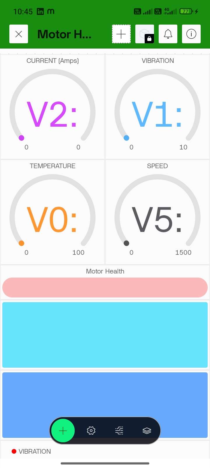 |  |
STEP 100: Open Event & Notifications Tab (better to use desktop) --> Click + New Event
STEP 101: Enter Event Name, Description, Choose Type "Critical ", and Enable notifications
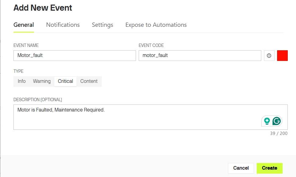
Note: Event trigger was already implemented in downloaded firmware file, So no need to alter that. Event name must exactly match with the name used on code.
STEP 102: The only thing to update the firmware is to enter the WiFi details. Open "config.h" and update the following lines in the code.
#define WIFI_SSID "YourWiFiName"
#define WIFI_PASS "YourPassword"

#define BLYNK_TEMPLATE_ID "YourTemplateID"
#define BLYNK_TEMPLATE_NAME "YourTemplateName"
#define BLYNK_AUTH_TOKEN "YourAuthToken"
STEP 103: Again, open Arduino IDE, Update Firmware, Power ON ESP32 --> Check LCD
Connecting to WiFi...     <---- Expected Result
Connected to WiFi
Blynk Connected
STEP 104: Run motor--> create controlled fault --> Verify Push Notification received.
MAKER NOTE: Internet required for notifications
- Even without WiFi ---> system still works (Edge AI)
- IoT is for remote monitoring + alerts only
NOTE: IOT Setup was done Sucessfully.
10.7 FINAL TESTING & VALIDATION
PRE-CHECK
- Firmware uploaded successfully
- Sensors calibrated and connected
- motor_model.h integrated.
- Blynk connected (ONLINE)
- Serial Monitor set to 115200 baud.
| STEP 105: TEST NORMAL CONDITION | STEP 106: TEST FAULT CONDITION |
|---|---|
| Run the motor under normal operation, and observe outputs | Introduce fault (imbalance/obstruction/load variation). Observe system response |
|
|
STEP 107: VERIFY SYSTEM RESPONSE
- Compare outputs across modules.
- Confirm synchronization
- Immediate alert response
- Accurate classification (NORMAL / WARNING / FAULT)
CAUTION
- Do not create unsafe faults (avoid electrical hazards).
- Ensure wires are secure during testing.
- Avoid prolonged overload on motor.
MAKER NOTE: Real-time validation confirms end-to-end system reliability.
10.8 DEMONSTRATION VIDEO:
For a complete working demonstration and real-time fault detection, kindly watch the video attached below. The video clearly shows system behaviour under normal and fault conditions.
10.9 USER NOTE:
MotorMind AI has been successfully designed and implemented.
If you have ideas for improvements, new features, or optimisations, feel free to explore and enhance the system. You are welcome to modify the firmware and experiment with your own innovations.
If you would like to contribute, you can create a branch or submit a pull request in the GitHub repository. I will review and merge valuable contributions.
This project is licensed under the PolyForm Noncommercial License on github. You are free to use, modify, and learn from this project for personal, academic, and research purposes.
Please note that commercial use of this project, including selling, licensing, or integrating it into commercial products or services, is not allowed without prior permission.
Let’s build and improve this system together.
11 PERFORMANCE INSIGHTS:
The MotorMind AI system demonstrated stable real-time performance under prototype conditions using a 55W table fan motor.
The Decision Tree model (TinyML) deployed on the ESP32 provided fast and consistent predictions with negligible latency. Since inference runs locally, the system responds instantly to changes in vibration, current, and temperature without any cloud dependency.
A key observation during development was the ADC2 limitation of ESP32 when WiFi is enabled. To avoid conflicts, all analog sensors were carefully mapped to ensure stable readings while maintaining IoT functionality via Blynk.
The use of feature extraction (RMS, mean, standard deviation) significantly improved classification reliability compared to raw sensor values. Stable separation between NORMAL and FAULT conditions was achieved during testing.
The dual-controller architecture (ESP32 + Arduino) improved performance:
- ESP32 --> sensing + AI inference
- Arduino --> LCD handling
This reduced processing overhead on ESP32 and ensured smooth real-time operation.
The project highlights that real-world embedded AI systems require careful coordination between hardware, firmware, and data quality.
12 COMMON MISTAKES AND DEBUGGING STRATEGY:
1) Using ADC2 pins while WiFi is enabled.
- Result: Incorrect or zero readings
- Fix: Use ADC1 pins only for analog sensors.
2) Connecting the ACS712 in parallel instead of in series.
- Result: Wrong current measurement.
- Fix: Always connect in series with the motor line.
3) Collecting data only in normal conditions.
- Result: Poor ML accuracy
- Fix: Collect balanced data for different conditions.
4) Loose vibration sensor, Incorrect IR alignment and incorrect adjustment.
- Result: Noisy or wrong readings
- Fix: Firm mounting + proper alignment
5) Wrong Auth Token, Incorrect virtual pin mapping.
- Result: No IoT data
- Fix: Match pins exactly with code.
6) Unstable supply or improper grounding.
- Result: Fluctuating readings.
- Fix: Use a stable supply + common ground.
7) Editing the dataset incorrectly.
- Result: Model confusion
- Fix: Use raw collected data only.
13 CONCLUSION:
MotorMind AI successfully demonstrates an intelligent and scalable approach to motor condition monitoring using Edge AI. By integrating multi-sensor data with on-device machine learning, the system is able to detect faults in real time without relying on cloud infrastructure.
The project validates that low-cost embedded platforms like ESP32 can be effectively used for predictive maintenance applications. The combination of sensor fusion, feature-based analysis, and lightweight AI models enables reliable fault detection while maintaining low latency and efficient resource usage.
The total cost of the MotorMind AI prototype is approximately ₹2100 (excluding the motor). The system is modular and non-intrusive, allowing easy deployment on existing motors, while industrial-scale implementation requires additional components such as current transformers and electrical isolation, increasing the overall cost.
Overall, the system achieves a complete workflow from data acquisition to intelligent decision-making, making it suitable for both educational purposes and real-world adaptation.
14 FUTURE SCOPE:
- Cloud-based data logging and long-term analytics. Not for detection, but for:
- Data storage
- Trend analysis
- Fleet monitoring
- Custom industrial mobile/web application with advanced UI and analytics.
- Use of advanced models (Random Forest, TinyML optimisation)
- Deployment on industrial-grade hardware with proper isolation
- Addition of advanced features such as anomaly trend analysis and adaptive learning.
NOTE:
This project was built out of a strong interest in developing intelligent embedded systems that can bridge the gap between electronics and real-world industrial challenges.
It reflects my curiosity towards combining hardware, data, and AI to create practical and impactful engineering solutions.
I will continue to enhance this project, and all future improvements will be updated in the repository.
I WAS CREATED TO CREATE!
BUILD...LEARN...INNOVATE...
Author
YUKESH S
Embedded Systems and PCB Design Enthusiast,
BE Electrical and Electronics Engineering,
2nd Year Student at College of Engineering (CEG Campus),
Anna University, Chennai,
Connect with me:
Email: [email protected]
LinkedIn: YUKESH S
GitHub: YUKESH0620
LINKS:
Project Repository: MotorMind-AI-v1.026
Learning Resources: ESP32 Platform on ElectronicWings
ACKNOWLEDGEMENT:
I would like to acknowledge the open-source community and various learning resources that supported the development of this project. Their contributions played an important role in understanding and implementing the concepts used in this work.
REFERENCES:
- ABB Group -- Industry Report on Industrial Downtime and Maintenance "Link"
- thyssenkrupp -- Predictive Maintenance and Industrial Digitalisation "Link"
- Towards Data Science -- Motor Fault Classification using Machine Learning "Link"
- PowerLine Magazine -- Real-time Monitoring and Predictive Maintenance in Motors "Link"