Imagine a motor that doesn’t just run -- but understands its own health and predicts failure in advance.
Instead of failing without warning, what if your motor could alert you before a fault becomes critical?
1. INTRODUCTION :
Industrial motors play a vital role in both domestic and industrial applications. However, unexpected failures caused by faults such as bearing damage, overheating, imbalance, and overcurrent can lead to costly downtime, reduced efficiency, and safety risks.
Traditional monitoring systems are mostly reactive, identifying issues only after failure occurs. This results in increased maintenance costs and unplanned shutdowns. Therefore, there is a need for an intelligent system that can continuously monitor motor health and detect faults at an early stage.
To address this challenge, this project presents MotorMind AI, an ESP32-based intelligent system for real-time motor fault detection using vibration, temperature, and current analysis. By integrating Edge AI, the system processes data locally without relying on cloud connectivity, ensuring faster response and reliable operation even in offline environments.
For prototyping purposes, a single-phase induction motor (table fan) is used in this project. However, the system is designed to be scalable and can be applied to industrial induction motors without changes in the core architecture.
2. PROBLEM STATEMENT:
Industrial motor failures are one of the major causes of unplanned downtime in industries. These failures not only interrupt production but also lead to significant financial losses and operational inefficiencies.

Figure 1: Industrial downtime cost analysis(Source: ABB – https://new.abb.com/news/detail/129763)
In many industries, motors operate continuously under varying loads and harsh environmental conditions. Faults such as bearing wear, overheating, mechanical imbalance, and overcurrent often develop gradually and remain undetected until they cause severe damage.
In real industrial environments, motor failures in equipment such as pumps, compressors, and conveyors can lead to a complete production shutdown. In some cases, a single motor failure can halt an entire process line, resulting in significant financial and operational losses.
According to industry studies, unplanned downtime can cost thousands to lakhs per hour depending on the scale of operation. Despite this, many existing systems rely on periodic inspection or manual monitoring, which are not sufficient for early fault detection.
Moreover, most advanced monitoring solutions depend on cloud-based processing, which introduces latency, requires continuous internet connectivity, and may not be suitable for remote or critical applications.
3. SOLUTION:
Therefore, there is a strong need for a real-time, intelligent, and standalone system that can:
- Continuously monitor motor health
- Detect faults at an early stage
- Operate without cloud dependency
- Provide reliable and fast decision-making
This project aims to solve these challenges by developing a compact and efficient Edge AI-based motor fault detection system.
MotorMindAI: ESP32-Based Intelligent Motor Health Monitoring System Using Edge AI
4. SYSTEM OVERVIEW:
The proposed system, MotorMind AI, is designed to monitor motor health in real time using multiple sensors and intelligent processing. The system collects data from different physical parameters of the motor and analyses them using Edge AI to detect potential faults.
The overall system consists of three main stages: data acquisition, signal processing, and intelligent fault detection.
4.1 SYSTEM ARCHITECTURE:
.png)
Figure 2: Overall system architecture of MotorMind AI
4.2 WORKING PRINCIPLE:
The system continuously monitors the motor using multiple sensors:
- Vibration sensor (ADXL345) to detect mechanical faults such as imbalance and bearing wear.
- Temperature sensor (DS18B20) to monitor overheating.
- Current sensor (ACS712) to detect overcurrent conditions.
- IR sensor to measure motor speed (RPM).
The collected sensor data is processed by the ESP32 microcontroller, where signal conditioning and feature extraction are performed. Important features such as RMS, mean, and peak values are derived from the signals.
These features are then fed into an Edge AI model, which predicts the health condition of the motor in real time without relying on cloud connectivity.
4.3 DECISION MAKING AND OUTPUT:
.png)
Figure 3: System workflow and decision-making process
Based on the AI model output:
- If abnormal conditions are detected, the system triggers:
- Fault indication using LEDs
- Audible alert using a buzzer
- Fault status display
2. If the motor operates normally:
- The system indicates a healthy status
The system can also display real-time information through display modules and serial monitoring.
5. HARDWARE SETUP:
The hardware setup of MotorMind AI is designed to capture multiple physical parameters of a motor and interface them with the ESP32 microcontroller for real-time monitoring and analysis.
The system integrates various sensors to monitor vibration, temperature, current, and motor rotational speed.
5.1) COMPLETE HARDWARE PROTOTYPE:
.jpg)
Figure 4.1: Complete hardware prototype setup of MotorMind AI
.jpg)
Figure 4.2: Complete working hardware prototype of the MotorMind AI system
This setup demonstrates the complete working prototype built using a single-phase induction motor (table fan). All sensors are mounted appropriately to capture real-time motor behaviour.
5.2) VIBRATION MONITORING - ADXL345:
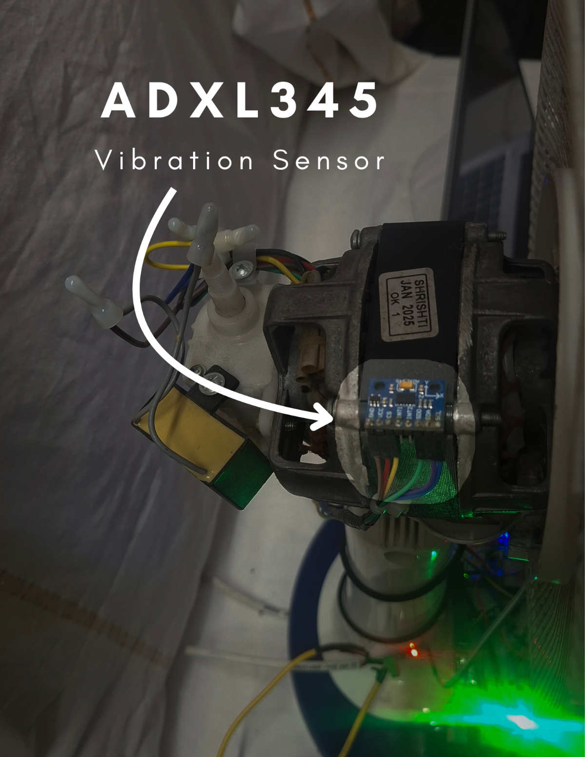
Figure 5: ADXL345 vibration sensor mounted on motor
The ADXL345 accelerometer is used to monitor motor vibrations.
- Detects imbalance and misalignment
- Captures multi-axis vibration data
Useful for mechanical fault detection
5.3) TEMPERATURE MONITORING - DS18B20:
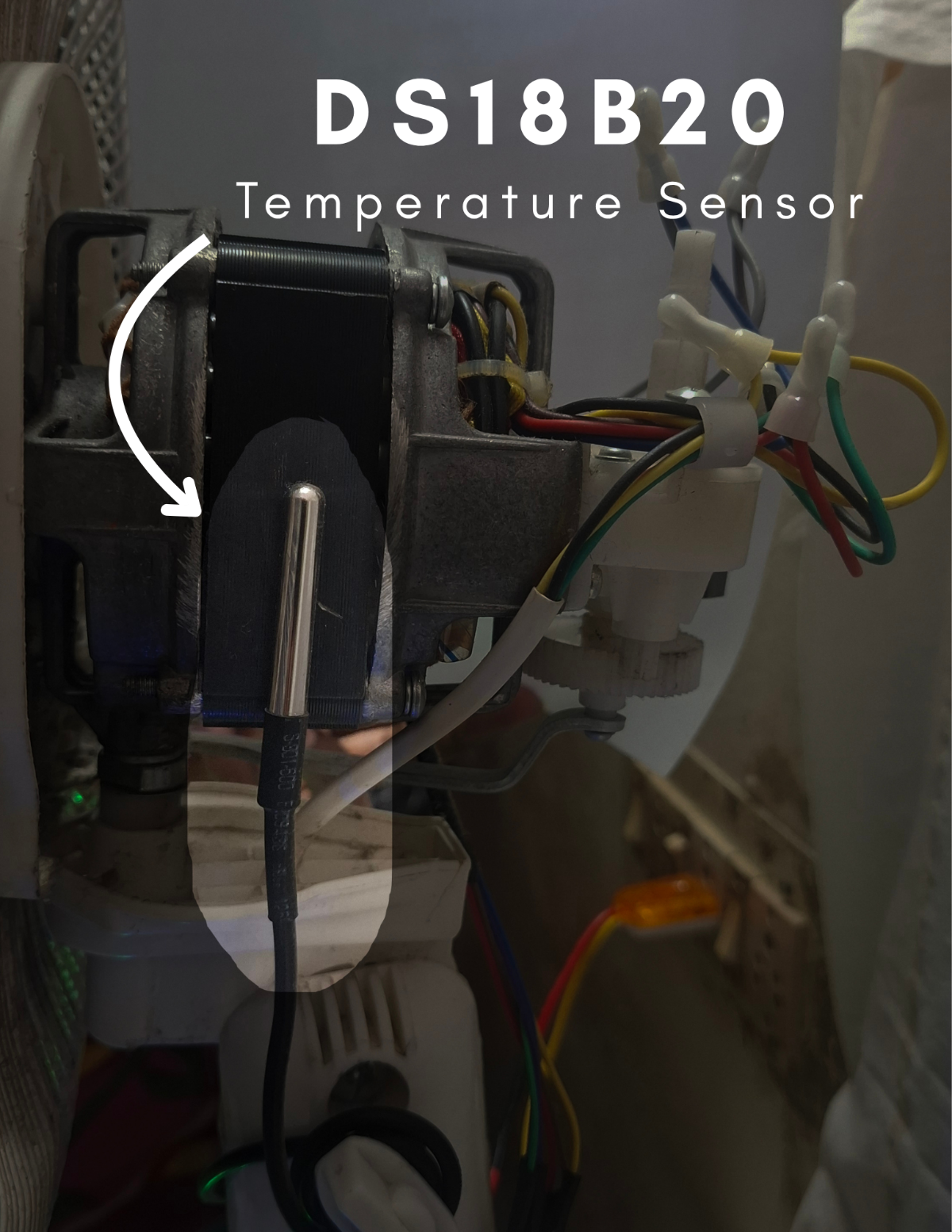
Figure 6: DS18B20 temperature sensor placed on motor
The DS18B20 temperature sensor monitors motor temperature continuously.
- High-accuracy digital temperature sensing.
- Helps detect overheating conditions.
Prevents thermal damage.
5.4) CURRENT MEASUREMENT - ACS712 20A :
.png)
Figure 7: ACS712 current sensor used for motor current monitoring.
The ACS712 20A current sensor is used to measure the motor current. It helps in detecting abnormal current conditions such as overload and overcurrent faults.
- Provides analog voltage proportional to current.
- Enables detection of electrical anomalies.
Essential for identifying early-stage faults.
5.5) RPM MEASUREMENT - IR SENSOR:
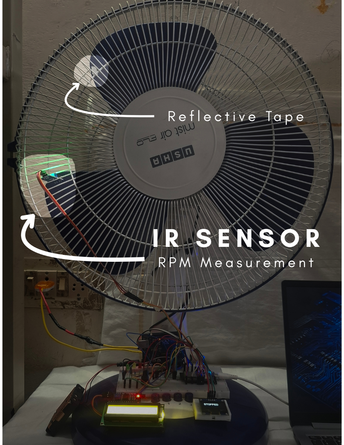
Figure 8: IR sensor used for RPM measurement with reflective tape.
The IR sensor module is used to measure motor speed (RPM).
- Detects reflective pulses from a rotating surface.
- Calculates rotational speed.
Useful for identifying speed variations.
5.6) CONTROL AND PROCESSING UNIT:
The ESP32 microcontroller acts as the central processing unit of the system.
- Reads sensor data in real time.
- Performs signal processing.
- Executes the Edge AI model.
Controls output indicators.
5.7) DISPLAY AND ALERT SYSTEM:
The system provides real-time feedback through displays and visual indicators to represent the motor health condition.
5.7.1) OLED DISPLAY OUTPUT:

Figure 9: OLED display showing real-time motor parameters
The OLED display presents live motor data, including vibration level, Current consumption, RPM (speed), Temperature, motor health and Overall motor Health status. This allows quick monitoring of system performance in real time.
5.7.2) LCD DISPLAY OUTPUT:
.jpeg)
Figure 10: LCD showing system status
The 16x2 LCD provides a simplified system-level output, such as:
- System name
- Motor status (NORMAL / OVERCURRENT / UNBALANCE / OVERHEAT)
- Connectivity status (e.g., offline mode)
5.7.3) LED INDICATION - NORMAL CONDITION:
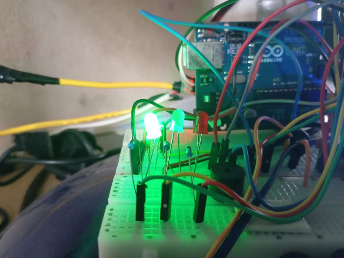
Figure 11: Green LED indication representing normal motor condition
The green LED glows when the motor is operating under normal conditions, indicating that all monitored parameters are within safe limits.
5.7.4) LED INDICATION - WARNING CONDITION:
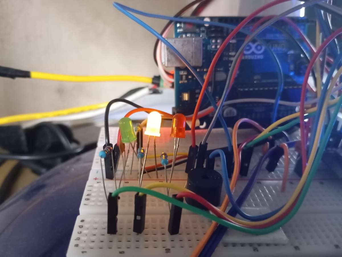
Figure 12: Yellow LED indicating a warning condition
The yellow LED indicates a warning state when certain parameters start deviating from normal ranges, providing an early alert before a critical failure occurs.
5.7.5) LED INDICATION - FAULT CONDITION:
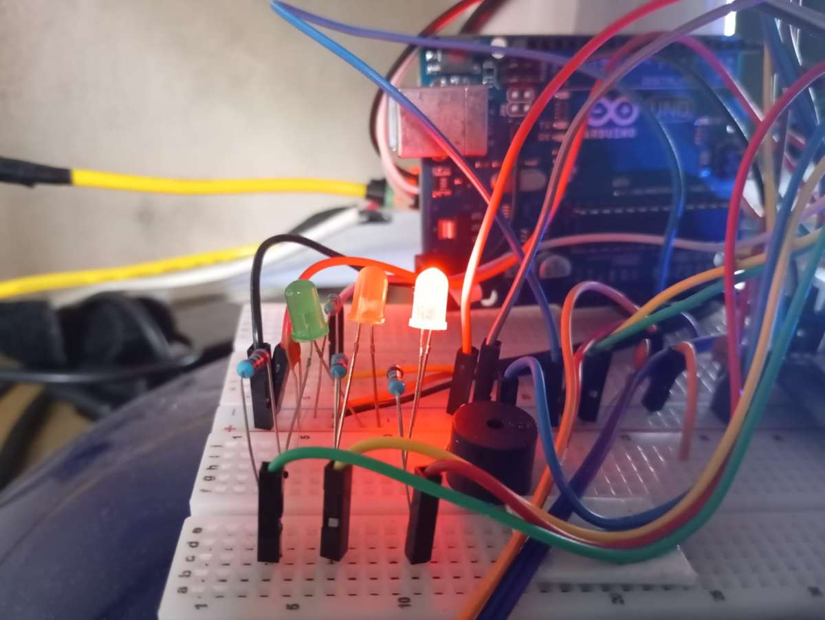
Figure 13: Red LED indicating fault condition
The red LED turns ON during critical fault conditions, accompanied by a buzzer alert, indicating immediate attention is required.
5.7.6) POWER SUPPLY AND SUPPORTING COMPONENTS:
The system is built using a breadboard for rapid prototyping, along with resistors and capacitors to ensure stable circuit operation. Connecting wires are used to establish proper electrical connections between all components.
The ESP32 is powered through a USB connection from a laptop, enabling both power supply and serial communication for programming and debugging. The Arduino Uno is powered using an external battery source, ensuring independent operation of peripheral components within the system.
6. CIRCUIT DIAGRAM:
The circuit design of MotorMind AI integrates multiple sensors and modules with the ESP32 microcontroller to enable real-time motor monitoring and fault detection.
This section presents both the practical breadboard implementation and the detailed schematic representation of the system.
6.1) BREADBOARD IMPLEMENTATION:
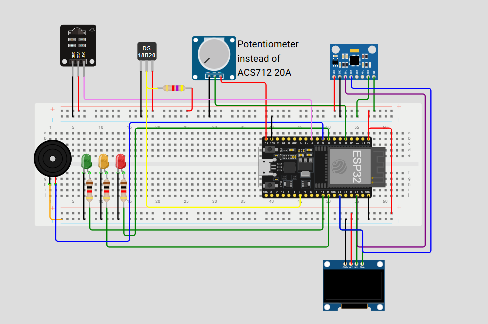
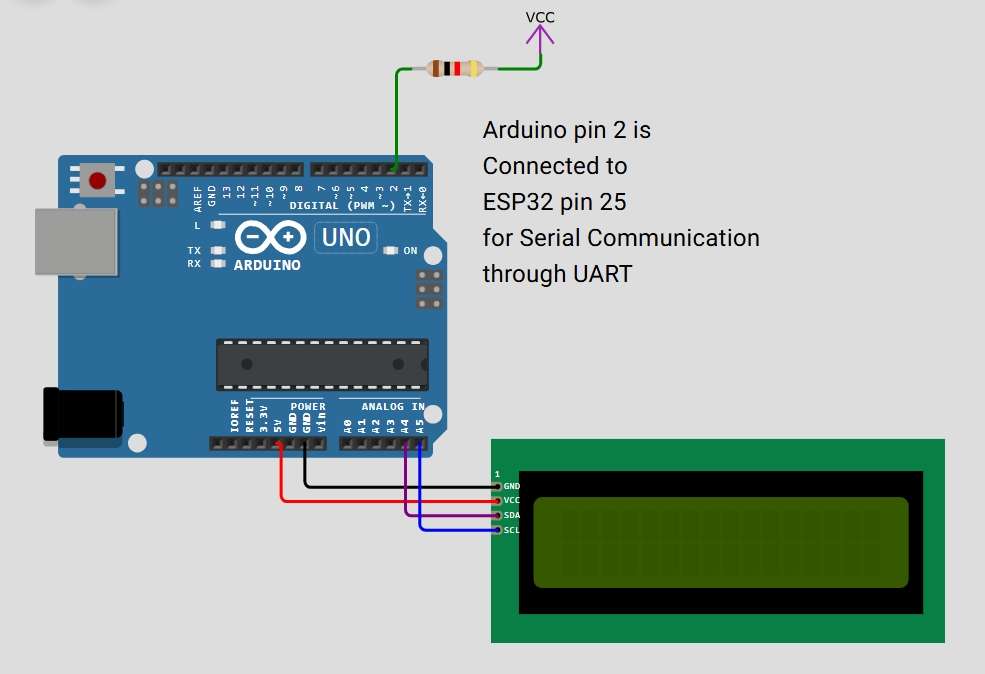
Figure 14: Breadboard-level circuit implementation of MotorMind AI
The breadboard diagram represents the practical wiring of all components, including sensors, displays, LEDs, and the microcontroller. It illustrates how each module is interconnected during the prototyping phase.
6.2) SCHEMATIC DIAGRAM:
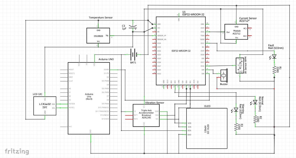
Figure 15: Schematic diagram of the complete system.
The schematic provides a clear electrical representation of the system, showing all connections, signal paths, and component interfacing in a structured manner.
6.3) ESP32 PIN CONFIGURATION:
The ESP32 microcontroller is interfaced with multiple sensors and modules. The key pin connections used in this project are:
Note: The ESP32 Wi-Fi feature is utilized for IoT connectivity using the Blynk platform. However, to maintain reliable analog readings (especially from the ACS712 current sensor), sensor data acquisition and processing are prioritized locally. This minimizes the impact of Wi-Fi-induced noise on ADC performance while still enabling remote monitoring.
| COMPONENTS | ESP32 PIN |
|---|---|
| IR Sensor (RPM) | GPIO27 |
| Current Sensor (ACS712) | GPIO34 |
| Temperature Sensor (DS18B20) | GPIO4 |
| Buzzer | GPIO26 |
| LED (Green) | GPIO18 |
| LED (Yellow) | GPIO19 |
| LED (Red) | GPIO33 |
| OLED Display (SDA) | GPIO21 |
| OLED Display (SCL) | GPIO22 |
| ADXL345 (SDA) | GPIO21 |
| ADXL345 (SCL) | GPIO22 |
| UART TX (ESP32 → Arduino) | GPIO25 |
| UART RX (Arduino) | D2 (Arduino's pin) |
| LCD (SDA) | A4 (Arduino's pin) |
| LCD (SCL) | A5 (Arduino's pin) |
| Note: The I2C protocol is used to interface multiple devices (OLED display and ADXL345 accelerometer) using shared SDA and SCL lines, reducing pin usage and improving hardware efficiency. A common ground is maintained between ESP32 and Arduino to ensure reliable UART communication and signal reference. | |
6.4) ESP32 PINOUT:
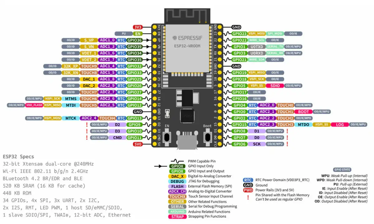
Figure 16: ESP32 development board pinout diagram (Source:https://robocraze.com/products/7semi-esp32-devkit-d-esp32-wifi-ble-development-board )
The above pin diagram provides a detailed overview of the ESP32 GPIOs used in this project. It helps in understanding the mapping between sensors, communication interfaces, and output devices.
6.5) ARDUINO UNO R3 PINOUT:
In this project, UART communication is established between the ESP32 and Arduino. The ESP32 transmits serial data through GPIO25 (TX), which is received by the Arduino on digital pin D2 using SoftwareSerial. This enables reliable data exchange between the two controllers.
(Source Link: https://docs.arduino.cc/hardware/uno-rev3)
Arduino UNO controls the LCD using the I2C interface (A4 - SDA, A5 - SCL). This separation helps distribute processing and improves system modularity.
7. SOFTWARE AND ML IMPLEMENTATION:
The MotorMind AI system integrates embedded software with machine learning to enable intelligent motor fault detection. The ESP32 performs real-time data acquisition, feature extraction, and on-device inference using a trained Decision Tree model. The system is designed with a modular software architecture, allowing separation of sensing, processing, machine learning, communication, and visualisation tasks.
The machine learning model is trained offline using collected sensor data and then converted into an embedded-compatible format (motor_model.h) for deployment on the ESP32. This enables Edge AI operation, where predictions are made locally without relying on cloud processing, ensuring low latency and high reliability.
The software architecture of MotorMind AI is designed to perform
- Real-time data acquisition,
- Signal Processing
- Feature Extraction
- Intelligent fault detection using Edge AI
- Decision Logic
- Output and Alerts
- Communication System
The ESP32 serves as the main processing unit, while the Arduino assists in display handling and communication.
The complete source code, dataset, and trained model files are available in the GitHub repository and Code section.
7.1 MACHINE LEARNING IMPLEMENTATION:
The machine learning pipeline consists of data collection, preprocessing, model training, and deployment. Sensor data such as vibration, current, temperature, and RPM are collected and stored in a dataset. This dataset is used to train a Decision Tree model that classifies motor conditions into different states, such as Normal, Warning, and Fault.
The trained model is then converted into a C-compatible header file (motor_model.h) using a conversion script, enabling deployment on the ESP32 for real-time inference.
MODEL DEPLOYMENT PIPELINE:
dataset.txt -> train_motor_model.py -> motor_fault_model.pkl -> convert_to_c.py -> motor_model.h -> ESP327.1.1) DATASET PREPARATION: "Dataset.txt"
The dataset used for training the machine learning model consists of 920 samples collected from the real-time operation of the motor setup. These samples capture both normal and abnormal operating conditions, enabling effective fault classification.
Each entry in the dataset contains the following parameters:
- time_ms – Timestamp of data acquisition (in milliseconds)
- vib_rms – Root Mean Square value of vibration
- vib_mean – Mean vibration value
- vib_std – Standard deviation of vibration (variation indicator)
- current_rms – RMS value of motor current
- current_mean – Average current consumption
- current_std – Current fluctuation
- rpm – Motor speed (rotations per minute)
- temp_C – Temperature in Celsius
status – Label indicating motor condition
7.1.1.1) DATASET STRUCTURE:
The dataset is structured in a tabular format, where:
- Each row represents one observation (one time instance)
- Each column represents a feature (sensor-derived parameter)
- The final column (status) acts as the target label
This structure follows the standard format required for supervised machine learning:
[Features] ----> [Label]
Where:
- Features = vibration, current, rpm, temperature
- Label = motor condition (e.g., STOPPED / NORMAL / FAULT)
7.1.1.2 ) FEATURE REPRESENTATION LOGIC:
X = [vib_rms, vib_mean, vib_std, current_rms, current_mean, current_std, rpm, temp_C]
y = status
The model learns to map input features (X) to the corresponding motor condition (y).
7.1.2) MODEL TRAINING SCRIPT: "train_motor_model.py"
This script is responsible for training the machine learning model using the collected dataset and preparing it for deployment in the embedded system.
This file performs the complete machine learning pipeline, including:
- Loading dataset
- Feature selection
- Data splitting
- Model training
- Evaluation
- Model saving
It converts raw sensor data into a trained model capable of classifying motor conditions.
KEY IMPLEMENTATION STEPS:
STEP 1: DATASET LOADING
data = pd.read_csv("dataset.txt")- Loads the collected sensor dataset.
- Uses structured CSV format for easy processing.
STEP 2: FEATURE AND LABEL SEPARATION
X = data.drop(["time_ms","status"], axis=1)
y = data["status"]- Features (X): vibration, current, RPM, temperature.
- Label (y): motor condition (Normal / Overcurrent / unbalance / overheat / Stopped).
STEP 3: TRAIN-TEST SPLIT
X_train, X_test, y_train, y_test = train_test_split(
    X, y, test_size=0.2, random_state=42
)- 80% ---> Training
- 20% ---> Testing
- Ensures unbiased evaluation
STEP 4: MODEL TRAINING ( DECISION LOGIC LEARNING )
model = RandomForestClassifier(n_estimators=100)
model.fit(X_train, y_train)- Uses tree-based classification (ensemble learning)
- Learns patterns from sensor data
- Internally forms decision rules (similar to Decision Tree logic)
STEP 5: MODEL EVALUATION
accuracy = accuracy_score(y_test, predictions)- Measures prediction accuracy
- Validates model performance before deployment
STEP 6: MODEL EXPORT
joblib.dump(model, "motor_fault_model.pkl")- Saves trained model as ( .pkl ) file
- This file is later converted into an embedded format
7.1.3) TRAINED MODEL FILE: "motor_fault_model.pkl"
This file contains the trained machine learning model generated after processing the dataset using the training script. It stores the learned patterns and decision logic required for motor fault classification. This file acts as a bridge between ML training and embedded deployment
This file is the serialised (saved) version of the trained model.
It is used to:
- Preserve trained knowledge
- Avoid retraining every time
- Enable conversion to embedded format
- Enable Edge AI without heavy libraries
- Keep ESP32 lightweight and efficient
FUTURE IMPROVEMENTS:
- Reduce model size for faster inference
- Use pruning to simplify decision trees
- Compare with lightweight models (Decision Tree only)
- Compress model for memory optimisation
7.1.4) MODEL CONVERSION SCRIPT: "convert_to_c.py"
This file is responsible for converting the trained machine learning model into a C-compatible format so that it can be deployed on the ESP32 microcontroller.
This file bridges the gap between:
- Python-based ML model (.pkl)
- Embedded system deployment (.h file)
It enables Edge AI inference on ESP32 without requiring Python or heavy ML libraries.
KEY IMPLEMENTATION STEPS:
STEP 1: LOAD TRAINED MODEL
model = joblib.load("motor_fault_model.pkl")- Loads the trained model file
- Uses joblib for deserialization
STEP 2: CONVERT MODEL TO C CODE
c_code = port(model)- Uses ( micromlgen ) library
- Converts ML model into pure C logic
- Generates decision rules in embedded format
STEP 3: SAVE AS HEADER FILE
with open("motor_model.h", "w") as f:
f.write(c_code)- Saves the converted model into a ( .h ) file
- This file will be included in the ESP32 firmware
7.1.5) EMBEDDED AI MODEL: "motor_model.h"
This file contains the final machine learning model converted into C code, which is directly deployed on the ESP32 for real-time motor fault prediction.
The file motor_model.h enables on-device inference by embedding the trained model logic into the microcontroller firmware.
- Eliminates the need for Python or external libraries
- Allows real-time decision making
- Forms the core of Edge AI in this project
7.1.5.1 ) INTERNAL STRUCTURE OF THE MODEL:
The model is implemented as a Decision Tree classifier, translated into nested conditional ( if-else ) statements in C++.
int predict(float *x) {
    if (x[6] <= 148.13) {
        return 3;
    }
    else {
        if (x[3] <= 0.244) {
            ...
        }
    }
}
7.1.5.2 ) FEATURE MAPPING:
Each element in the input array x[ ] corresponds to a specific feature extracted from sensor data:
x[0] → vib_rms        (Vibration RMS)
x[1] → vib_mean       (Vibration Mean)
x[2] → vib_std        (Vibration Standard Deviation)
x[3] → current_rms    (Current RMS)
x[4] → current_mean   (Current Mean)
x[5] → current_std    (Current Standard Deviation)
x[6] → rpm            (Motor Speed)
x[7] → temp_C         (Temperature)
Note: This mapping must exactly match your dataset and feature extraction logic.
7.1.5.3 ) WORKING MECHANISM:
The prediction process follows these steps:
- Sensor values are collected from the motor.
- Features are computed (RMS, mean, standard deviation).
- Features are stored in an array x[ ].
- The predict( ) function is called.
- Decision tree logic evaluates input values.
- A class label is returned.
7.1.5.4 ) OUTPUT CLASSIFICATION:
The model outputs an integer representing motor condition:
0 --> Normal
1 --> Overcurrent
2 --> Overheat
3 --> Unbalance
4 --> Stopped
These values are later mapped to:
- LED indicators
- Display messages
- Alerts
Insights: The conversion of a trained machine learning model into embedded C logic demonstrates a complete Edge AI workflow. This enables real-time, reliable, and autonomous fault detection directly on the ESP32, making the system suitable for industrial deployment without cloud dependency.
7.2 SOURCE CODE ARCHITECTURE v2:
OVERVIEW:
The MotorMind AI firmware is designed using a modular programming approach, where each functionality is separated into independent files. This improves code readability, maintainability, and scalability.
Instead of writing everything in a single file, the system is divided into modules, such as:
- Sensor handling
- Feature extraction
- Machine learning inference
- Alert system
- Display control
- IoT communication
The main file (MotorMindAI.ino) serves as the central controller, integrating all these modules.
Note: The project was initially developed as a single-file implementation (Version 1), where all functionalities such as sensor handling, feature extraction, machine learning inference, and output control were written in one file.
To improve scalability, readability, and maintainability, the system was later redesigned into a modular architecture (Version 2). Both versions of the source code are available in the GitHub repository for reference and comparison.
DATA FLOW:
Sensors -> Feature Extraction -> ML Model -> Decision -> Output + Alerts + IoT7.2.1 CONFIGURATION MODULE: "config.h"
OVERVIEW:
This file serves as the central configuration module of the MotorMind AI system. It defines all system parameters, including pin assignments, sensor thresholds, communication settings, and system constants.
This file ensures that all configuration values are maintained in a single location, improving code readability, maintainability, and scalability.
PURPOSE:
- Centralised system configuration
- Define hardware pin mapping
- Set operational thresholds
- Store Wi-Fi and IoT credentials
- Control system behaviour
Acts as the foundation of the entire firmware.
Insight: " The configuration module demonstrates a well-structured firmware design by centralizing all system parameters. This approach improves flexibility, simplifies debugging, and reflects industry-standard embedded system practices."
7.2.2 MAIN FIRMWARE: " MotorMindAI.ino "
OVERVIEW:
This is the core execution file of the entire system. It controls:
- System initialization
- Sensor data flow
- Feature extraction
- ML prediction
- Output handling
- Communication
It acts as the brain that connects all modules.
7.2.2.1 STRUCTURE OF THE PROGRAM
The firmware follows the standard Arduino structure:
void setup() {
    // Initialization
}

void loop() {
    // Continuous execution
}
7.2.2.2 SYSTEM INITIALIZATION ( setup() )
- Initialize sensors
- Start serial communication
- Initialise displays (OLED / LCD)
- Set up GPIO pins (LEDs, buzzer)
- Initialise communication (UART / I2C / Blynk)
void setup()
{
    Serial.begin(115200);
    Serial2.begin(9600, SERIAL_8N1, -1, 25);

    Wire.begin(SDA_PIN, SCL_PIN);
    pinMode(LED_NORMAL, OUTPUT);
    ...
}
This ensures all hardware components are ready before execution starts.
7.2.2.3 MAIN EXECUTION LOOP ( loop() )
This is where the entire system workflow happens continuously.
STEP-BY-STEP WORKFLOW:
STEP 1: SENSOR DATA ACQUISITION
Reads real-time values from:
- Vibration sensor
- Current sensor
- Temperature sensor
- RPM sensor
readSensors();STEP 2: FEATURE EXTRACTION
Converts raw signals into meaningful features:
- RMS
- Mean
- Standard deviation
extractFeatures();STEP 3: MACHINE LEARNING PREDICTION
Calls the model from "motor_model.h"
prediction = model.predict(features);This is where Edge AI happens.
STEP 4: OUTPUT HANDLING
- Displays results on OLED / LCD
- Updates motor health status
updateDisplay(prediction);STEP 5: ALERT SYSTEM
Activates:
- LEDs
- Buzzer
triggerAlerts(prediction);STEP 6: IOT COMMUNICATION
- Sends data to Blynk via Wi-Fi
sendToBlynk();Insight: " The main firmware (MotorMindAI.ino) acts as the central controller of the system, integrating sensing, feature extraction, machine learning inference, health estimation, and output control into a continuous real-time workflow. Its modular structure ensures efficient data processing, low-latency operation, and easy scalability for future enhancements."
7.2.3 SENSOR MODULE: "sensors.h"
This file handles all sensor-related operations in the MotorMind AI system. It is responsible for acquiring raw data from multiple sensors and converting it into meaningful features such as RMS, mean, and standard deviation.
This module integrates:
- ADXL345 (vibration sensor)
- ACS712 (current sensor)
- DS18B20 (temperature sensor)
- IR sensor (RPM measurement)
SENSOR INTEGRATION:
The module initializes and manages the following sensor interfaces:
- I2C communication → ADXL345 accelerometer
- OneWire protocol → DS18B20 temperature sensor
- Analog input (ADC) → ACS712 current sensor
- Interrupt-based input → IR sensor for RPM
7.2.3.1 RPM MEASUREMENT: ( Interrupt-based )
The IR sensor generates pulses for each rotation. These pulses are counted using an interrupt function to ensure accurate real-time measurement.
void IRAM_ATTR countPulse()- Triggered on every pulse
- Uses time filtering to remove noise
- Updates pulse count safely
RPM CALCULATION:
float rawRPM = (count * 60000.0) / elapsed;
filteredRPM = 0.7 * filteredRPM + 0.3 * rawRPM;- Converts pulse count → RPM
- Applies low-pass filtering for stability
- Reduces noise and fluctuations
7.2.3.2 TEMPERATURE MEASUREMENT:
tempSensor.requestTemperatures();
return tempSensor.getTempCByIndex(0);- Uses DS18B20 digital sensor
- High-accuracy temperature reading
- Simple and reliable implementation
7.2.3.3 VIBRATION FEATURE EXTRACTION:
This module computes statistical features from vibration data.
vibMean = vibSum / VIBRATION_SAMPLES;
vibRMS = sqrt(vibSumSquares / VIBRATION_SAMPLES);
vibStdDev = sqrt((vibSumSquares / VIBRATION_SAMPLES) - (vibMean * vibMean));
Features Extracted:
- Mean --> average vibration
- RMS --> energy of vibration
- Standard deviation --> variation level
These features are critical for ML model accuracy.
7.2.3.4 CURRENT MEASUREMENT: ( ACS712 20A )
float voltage = (adcValue * 3.3) / 4095.0;
float current = (voltage - offsetVoltage) / ACS712_SENSITIVITY;
FEATURE CALCULATION:
currentMean = currentSum / validSamples;
currentRMS = sqrt(currentSumSquares / validSamples);
currentStdDev = sqrt((currentSumSquares / validSamples) - (currentMean * currentMean));- ADC-based current sensing
- Offset compensation applied
- Noise filtering:
if(abs(current) < 0.05) current = 0;- Invalid readings removed:
if(adcValue > 4000 || adcValue < 10) continue;This improves reliability significantly.
Insight: " The sensor module not only acquires raw data but also performs real-time feature extraction, transforming physical signals into machine learning–ready inputs. This significantly enhances the accuracy and efficiency of the fault detection system. "
7.2.4 SENSOR CALIBRATION MODULE: " calibration.h "
OVERVIEW:
This file is responsible for calibrating sensor readings to improve measurement accuracy. It ensures that sensors start from a correct baseline before normal operation, eliminating systematic errors.
Currently, this module implements offset calibration for the ACS712 current sensor, which is critical for accurate current measurement.
PURPOSE:
- Remove sensor offset errors
- Improve measurement accuracy
- Prevent false readings
- Ensure reliable input for the ML model
7.2.4.1 NEED FOR CALIBRATION:
In real-world sensors:
- Output is not perfectly zero at no input
- Manufacturing variations introduce offsets
Example (ACS712 20A):
- Ideal: 2.5V at 0A
- Actual: 2.48V / 2.53V (varies)
Without correction:
- The system may detect false current.
- Leads to wrong fault prediction.
7.2.4.2 CURRENT SENSOR CALIBRATION:
void calibrateCurrentSensor()CORE IMPLEMENTATION:
for(int i = 0; i < 500; i++)
{
    float voltage = (analogRead(CURRENT_PIN) * 3.3) / 4095.0;
    sum += voltage;
}
OFFSET CALCULATION:
offsetVoltage = sum / 500.0;FORMULA USED: (This removes baseline error completely)
Current = (MeasuredVoltage - OffsetVoltage) / SensitivityNote: Calibration must be performed when the motor is OFF, No load connected, and Stable ower Supply. Otherwise calibration becomes incorrect.
Insights: " The inclusion of a calibration module demonstrates a strong understanding of real-world sensor behavior. By compensating for hardware inaccuracies, the system ensures reliable data acquisition, which directly enhances the performance of the machine learning model and overall system accuracy."
7.2.5 FEATURE EXTRACTION MODULE: " features.h "
This file is responsible for organising and preparing sensor data into a structured format suitable for machine-learning inference. It acts as a bridge between raw sensor data and the ML model by converting extracted features into a standardised feature vector.
PURPOSE:
- Store extracted features in a structured format
- Convert features into an array format required by the ML model
- Ensure correct feature ordering for prediction
7.2.5.1 FEATURE STRUCTURE DEFINITION:
struct MotorFeaturesThis structure groups all extracted features into a single entity.
Included Features:
1. Vibration:
- RMS, Mean, Standard deviation
2. Current:
- RMS, Mean, Standard deviation
3. Motor Parameters:
- RPM
- Temperature
This matches exactly with the dataset features.
7.2.5.2 FEATURE VECTOR CONSTRUCTION:
features[0] = f.vibRMS;
features[1] = f.vibMean;
features[2] = f.vibStdDev;

features[3] = f.currentRMS;
features[4] = f.currentMean;
features[5] = f.currentStdDev;

features[6] = f.rpm;
features[7] = f.temperature;
Note: This Feature Mapping must match the Dataset ( dataset.txt ) and ML model ( motor_model.h ). Any mismatch leads to wrong predictions
7.2.5.3 FEATURE ARRAY BUILDER:
buildFeatureArray(MotorFeatures &f, float features[8]);- Converts structured data --> array format
- Prepares input for:
model.predict(features);7.2.5.4 NORMALIZATION ( FUTURE SUPPORT )
void normalizeFeatures(float features[8])- Allows scaling of features
- Useful for advanced ML models
Insight: " The feature extraction module ensures a consistent and structured transformation of sensor data into machine learning–compatible input. This guarantees reliable predictions and seamless integration between embedded firmware and the trained model. "
7.2.6 AI ENGINE MODULE: " ai_engine.h "
This file is responsible for executing machine learning inference and converting model predictions into meaningful motor fault conditions. It integrates the trained Decision Tree model (motor_model.h) with real-time logic to ensure reliable and stable fault detection.
PURPOSE:
This module performs three key functions:
- Run ML model inference
- Classify predicted output into fault types
- Confirm faults using multi-cycle validation logic
It acts as the decision-making brain of the system
7.2.6.1 AI MODEL INTEGRATION:
#include "motor_model.h"
extern Eloquent::ML::Port::DecisionTree model;- Imports an embedded ML model
- Uses Decision Tree inference
- Enables real-time prediction
7.2.6.2 AI INFERENCE EXECUTION:
int runAI(float features[8]) {
    return model.predict(features);
}- Takes a feature vector as input
- Returns predicted class (integer)
This is the actual ML execution step (Edge AI).
7.2.6.3 FAULT CLASSIFICATION:
String classifyFault(int aiPrediction)MAPPING:
0 --> Normal
1 --> Overcurrent
2 --> Overheat
3 --> Unbalance
4 --> Stopped
Converts numeric ML output to a meaningful fault type.
7.2.6.4 FAULT CONFIRMATION LOGIC:
This is a smart engineering addition that improves reliability.
if(abnormalCount >= ABNORMAL_CONFIRM_COUNT)
{
    return detectedFault;
}
Step-by-step working :
- The model predicts the condition
- Fault type is identified
- System checks if the abnormal condition persists
- Fault is confirmed only after multiple cycles
Abnormal Detection:
if(detectedFault != "NORMAL")
    abnormal = true;
Cycle Counting: ( Prevents false alarms due to noise )
if(abnormal)
    abnormalCount++;
else
    abnormalCount = 0;
Motor Stopped Detection: ( Special Case )
if(rpm < RPM_MIN_VALID)
{
    abnormalCount = 0;
    return "STOPPED";
}- Detects motor OFF condition
- Avoids false fault detection
Speed Validation Logic:
if(rpm > 250)- Fault detection only when the motor is running
- Prevents invalid predictions
Insights: " The AI engine not only performs machine learning inference but also incorporates validation logic to ensure reliable fault detection. By combining AI predictions with temporal confirmation, the system minimizes false positives and achieves robust real-time performance suitable for industrial environments. "
7.2.7 MOTOR HEALTH MODEL MODULE: "health_model.h"
OVERVIEW:
This file is responsible for calculating the overall motor health, estimating the remaining useful life (RUL), and providing maintenance recommendations based on real-time sensor data.
This module enhances the system by adding predictive maintenance capability, going beyond fault detection to estimate how long the motor can operate safely.
PURPOSE:
- Calculate motor health percentage
- Estimate remaining useful life (RUL)
- Provide maintenance recommendations
- Smooth health fluctuations
7.2.7.1 MOTOR HEALTH CALCULATION:
float computeMotorHealth(...)STEP 1: NORMALIZE PARAMETERS (Converts sensor values into relative stress levels)
float vibRatio = vibStdDev / VIBRATION_THRESHOLD;
float currentRatio = currentRMS / CURRENT_THRESHOLD;
float tempRatio = temperature / TEMPERATURE_THRESHOLD;
STEP 2: STRESS CALCULATION(Smart weighting based on fault impact)
if(vibRatio > 0.6)
vibStress = (vibRatio - 0.6) * 50;- Weightage: Vibration --> 50%
if(currentRatio > 0.6)
currentStress = (currentRatio - 0.6) * 30;- Weightage: Current --> 30%
if(tempRatio > 0.7)
tempStress = (tempRatio - 0.7) * 20;- Weightage: Temperature --> 20%
STEP 3: HEALTH COMPUTATION: (Higher stress to lower health)
float rawHealth = 100 - (vibStress + currentStress + tempStress);STEP 4: SMOOTHING FILTER: (Reduces fluctuations and noise)
float filteredHealth = 0.3 * rawHealth + 0.7 * previousHealth;STEP 5: LIMITING RANGE: (Keeps value within 0–100%)
if(filteredHealth > 100) filteredHealth = 100;
if(filteredHealth < 0) filteredHealth = 0;
7.2.7.2 REMAINING USEFUL LIFE (RUL):
int estimateRUL(float motorHealth)Logic: (Converts health to estimated life percentage)
int RUL = motorHealth * 1.2;
7.2.7.3 MAINTENANCE RECOMMENDATION:
String maintenanceAdvice(int RUL)OUTPUT: (Provides actionable insights)
RUL > 80 --> Healthy
RUL > 50 --> Service Soon
Else --> Immediate Maintenance Required
Insight: "The motor health model extends the system from fault detection to predictive maintenance by estimating the remaining useful life and providing actionable maintenance recommendations. This significantly enhances the practical value of the system for industrial applications."
7.2.8 ALERT SYSTEM MODULE: " alerts.h "
OVERVIEW:
This file is responsible for handling all output alert mechanisms in the MotorMind AI system. It translates the AI prediction results into physical indications using LEDs and a buzzer, enabling clear and immediate user feedback.
This module ensures that the system communicates motor health conditions effectively in real time.
PURPOSE:
- Indicate motor condition using LEDs
- Trigger buzzer during fault conditions
- Handle warning state logic
- Provide clear visual and audible feedback
This module represents the human interface of the system
7.2.8.1 ALERT COMPONENTS
This system uses:
- GREEN LED --> Normal condition
- YELLOW LED --> Warning condition
- RED LED --> Fault condition
- BUZZER --> Critical alert indication
7.2.8.2 WARNING STATE DETECTION:
bool checkWarningState(float motorHealth)if(motorHealth < HEALTH_WARNING_LEVEL && motorHealth >= 0)
return true;- Evaluates motor health percentage
- Detects early-stage abnormal conditions
This provides pre-fault warning capability
7.2.8.3 ALERT OUTPUT CONTROL:
void updateAlerts(String fault, bool warningState)This function controls all output devices based on the system state.
7.2.8.4 WORKING LOGIC (PRIORITY-BASED):
The alert system follows a priority hierarchy:
STOPPED CONDITION: " Prevents false alerts when the motor is not running "
if(fault == "STOPPED")- All LEDs OFF
- Buzzer OFF
- System inactive
FAULT CONDITION (HIGHEST PRIORITY): " Immediate attention required "
else if(fault != "NORMAL")- Red LED ON
- Buzzer ON
- Other LEDs OFF
WARNING CONDITION: " Early indication before failure "
else if(warningState)- Yellow LED ON
- Buzzer OFF
NORMAL CONDITION: " System operating safely "
else- Green LED ON
- All others OFF
Insights: " The alert system translates AI-based fault detection into intuitive visual and audible signals. By implementing a priority-based logic and multi-level indication system, it ensures reliable and user-friendly monitoring suitable for real-world applications."
7.2.9 DISPLAY AND COMMUNICATION MODULES: " display_oled.h & lcd_serial.h "
OVERVIEW:
These modules handle the visualization and external communication of motor data in the MotorMind AI system. They provide both real-time graphical display (OLED) and serial communication to Arduino for LCD output, ensuring clear and user-friendly monitoring.
PURPOSE:
- Display real-time motor parameters
- Show motor health status visually
- Communicate system status to external display (LCD via Arduino)
- Improve user interaction and monitoring
SYSTEM FLOW:
AI Output -> OLED Display(Detailed View) -> UART -> Arduino -> LCD Display(Simple View)7.2.9.1 OLED DISPLAY MODULE:
The OLED display is used as the primary monitoring interface, showing detailed motor parameters and system status.
STARTUP SCREEN: ( Enhances user experience and professionalism )
display.drawBitmap(0, 0, syk_logo, 128, 64, WHITE);- Displays project logo
- Shows system name and version
- Provides startup feedback
STOPPED STATE DISPLAY:
display.println("STOPPED");- Indicates motor is not running
- Prevents confusion with fault condition
HEALTH BAR VISUALIZATION:
int barWidth = map(motorHealth, 0, 100, 0, 40);- Converts motor health (%) ---> graphical bar
- Provides quick visual understanding
- Updates dynamically
REAL-TIME DATA DISPLAY:
displayMotorData(...)Displayed Parameters :
- Vibration (RMS)
- Current (RMS)
- RPM
- Temperature
- Motor Health (%)
- Fault Status
Provides complete system insight in real time.
7.2.9.2 LCD SERIAL COMMUNICATION MODULE:
This module enables communication between the ESP32 and Arduino using UART, allowing the Arduino to display simplified messages on an LCD.
MESSAGE TRANSMISSION:
Serial2.println(msg);- Sends status messages to Arduino
- Uses UART communication
- Enables the external display system
DUPLICATE MESSAGE PREVENTION:
if(msg != lastLCDmsg)- Prevents repeated data transmission
- Reduces communication overhead
- Improves system efficiency
Insights: " The system integrates both graphical and serial display mechanisms to provide comprehensive and user-friendly monitoring. The OLED offers detailed real-time visualization, while the LCD ensures simplified external display, making the system suitable for both technical and non-technical users."
7.2.10 IOT AND REMOTE MONITORING MODULE: " iot_blynk.h "
OVERVIEW:
This file enables IoT functionality in the MotorMind AI system by connecting the ESP32 to the Blynk platform. It allows real-time remote monitoring of motor parameters, alert notifications, and system status visualization through a mobile dashboard.
PURPOSE:
- Send real-time sensor data to Blynk
- Display motor health and status remotely
- Trigger fault alerts via mobile notification
- Manage Wi-Fi connectivity automatically
- This module transforms the system into an Industrial IoT solution.
7.2.10.1 DATA TRANSMISSION TO BLYNK:
void sendDataToBlynk()
{
   Blynk.virtualWrite(V0, temperature);
   Blynk.virtualWrite(V1, vibration);
   Blynk.virtualWrite(V2, current);
   ...
}
Provides complete remote monitoring capability.
7.2.10.2 FAULT ALERT NOTIFICATION: (no spamming)
void checkMotorAlert(float motorHealth)LOGIC:
if (motorHealth < HEALTH_CRITICAL_LEVEL && !alertSent)FEATURES:
- Sends notification using:
Blynk.logEvent("motor_fault", "Motor health critical!");- Prevents repeated alerts:
alertSent = true;Resets when the condition improves.
7.2.10.3 WIFI MANAGEMENT SYSTEM:
void manageWiFi()WHEN CONNECTED:
if (WiFi.status() == WL_CONNECTED)- Updates LCD:
sendLCD("WIFI:CONNECTED");- Connects to Blynk:
Blynk.config(BLYNK_AUTH_TOKEN);
Blynk.connect();
WHEN DISCONNECTED:
WiFi.begin(WIFI_SSID, WIFI_PASS);Retries every 10 seconds
- Updates LCD:
sendLCD("WIFI:RETRY");- Shows status:
sendLCD("BLYNK:OFFLINE");
...continued on part 2
This project documentation is presented in two parts for better clarity and structured explanation.
Part 1 (this page) covers the complete system design, including hardware setup, circuit implementation, software architecture, and machine learning integration.
The continuation (Part 2) includes:
- Software architecture ( balance ) <----- Continued here
- Output results and observations.
- What makes it different.
- Step-by-step system development workflow (complete build process).
- Performance insights and Debugging stratergy.
- Conclusion and future scope.
- Acknowledgement and References.
CONTINUE: MotorMindAI v1 Part 2
Note: The complete step-by-step project building procedure are covered in Part 2.