




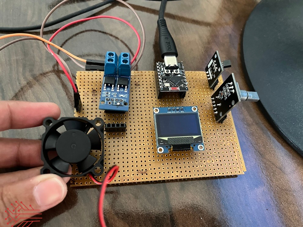
Description:
Problem Statement:
Food distribution companies operating cold storage facilities face critical challenges with traditional monitoring systems:
- No real-time visibility into temperature
- Manual data logging leads to human errors
- No remote access or mobile alerts
- Difficult and expensive to scale across multiple storage units
What This Project Does:
This project builds a smart cold storage monitoring system using ESP32 and BLE (Bluetooth) protocol, enabling real-time monitoring and automation.
- Monitors temperature in real-time
- Displays data on OLED screen
- Sends data to IoT platforms (Matter supported apps)
- Automatically controls cooling system as per the threshold set
- Triggers Fan automatically, when temperature exceeds threshold
- Easily scalable for multiple storage units
Technology Stack:
Hardware: ESP32, Temperature Sensor, OLED, Peltier, Fan, Power management
Firmware: ESP-IDF(C/C++) and Arduino IDE
Protocol: Wi-Fi and BLE (Bluetooth)
Platforms: Apple Home, Google Home, SmartThings
App: Android (Flutter and React Native)
Prerequisites:
- ESP32 Development Board
- Temperature DS18B20 Sensor
- ESP-IDF installed or Arduino IDE
- Wi-Fi / BLE (Bluetooth) network
- Android device
- Smart Home account (Google / Apple / Samsung)
Step-by-Step Project Implementation
Step 1: Collecting Components
In this step, I collected all hardware components required for the project.
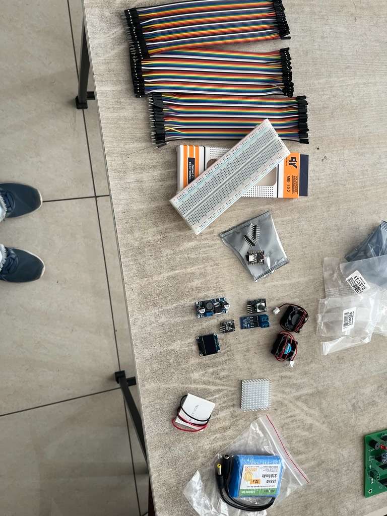
- Jumper wires set
- Breadboard
- ESP32 board
- OLED display
- Relay module
- Power module
- Cooling components
This ensures all required parts are ready before building the circuit.
Step 2: Breadboard Testing (Prototype Stage)
I first tested the circuit on a breadboard to verify functionality.
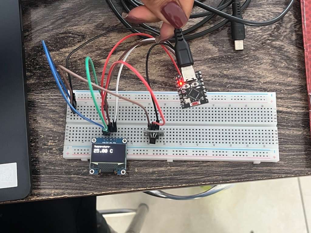

What you did :
- ESP32 connected via USB
- OLED display connected (I2C)
- Sensor connected to GPIO
- Temperature displayed (~25°C)
This step confirm:
- Sensor working
- OLED working
- Code running correctly
Step 3: PCB Assembly (Permanent Circuit)
After successful testing, I assembled the circuit on a PCB board.
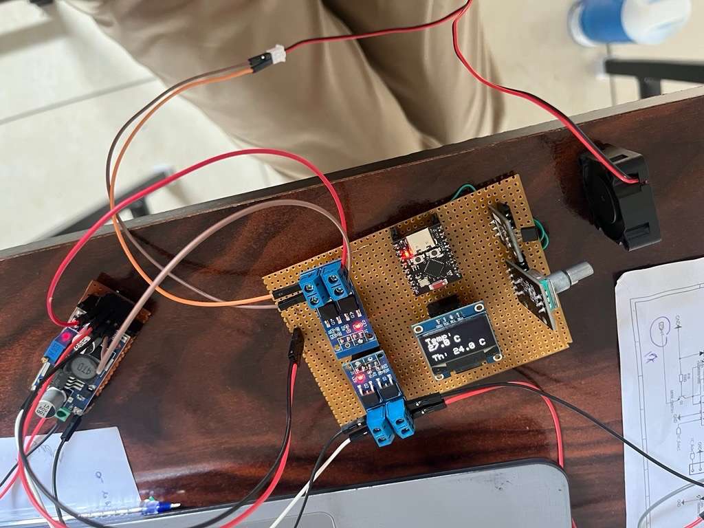
From your setup:
- ESP32 mounted on PCB
- MOSFET module connected for Fan Control
- OLED fixed on board
- Proper wiring connections
This makes the system:
- Durable
- Stable
- Ready for deployment
Step 4: Cooling System Integration
Next, I connected the cooling system (Fan + Peltier module).
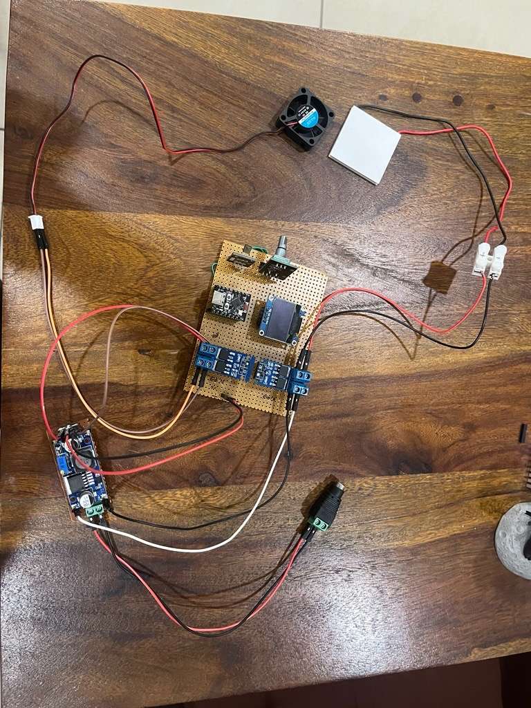
- Cooling fan connected with MOSFET
- Peltier module connected with MOSFET
Working:
- High temperature → MOSFET → Cooling ON
- Normal temperature → Cooling OFF
Step 5: Final System Integration
In the final step, all components are integrated to build a complete working system.
Final System Includes:
- ESP32 controller
- OLED display
- Temperature sensor
- MOSFET module
- Cooling system
- Power supply
Working Principle:
- The temperature sensor continuously reads real-time data.
- ESP32 processes the received values and controls the system accordingly.
The OLED display shows live temperature readings.
If temperature exceeds the defined threshold, the MOSFET is activated and the cooling system turns ON.
When the temperature returns to normal, the cooling system is turned OFF automatically.
Features:
- Real-time temperature monitoring
- Automatic cooling control
- IoT based smart system using BLE and Wi-Fi protocol
- OLED display output
Conclusion:
This project demonstrates a smart and efficient cold storage monitoring system using ESP32 and BLE (Bluetooth) protocol. It reduces manual effort, improves accuracy, and ensures proper temperature control through automation.
Update: Updated the Next version of same project with nrf52832 to save the battery life with matter protocol.


