
Greetings everyone and welcome back! This is the "Wand of Illumination, " a 3D-printed wand combined with a flashlight incorporated inside.

Utilizing one of the Harry Potter wands as a model, we have created a new wand from scratch. Inside the wand, we then installed a fully operational flashlight circuit.
An Attiny13A 8-bit microprocessor connected to a switch that toggles the white 5mm LED makes up the flashlight circuit. A 3.7V, 50mAh LiPo cell that we added inside the wand serves as the power source. The TP4056 IC configuration, a well-known Li-ion/LiPo charging IC, is used to charge the LiPo cell.
Using the sketch we uploaded to the Attiny, the user can flip an LED on or off by pressing the switch for 500 milliseconds. If the user presses the switch again, the LED will turn off.
This article is about the whole build process of this wand, so let's get started with the build.
Materials Required
Here are a few components that we used in this build.
- Attiny13A MCU
- Custom PCB (Provided by PCBWAY)
- TP4056
- 1uF Capacitor 1206 Package
- 3.7V 50mAh LiPo Cell
- Custom 3D-printed body in Brown PLA
- 1k Resistor 0603 Package
- Green LED 0603
- Red LED 0603
- 2 Ohms Resistor 1206
Design Breakdown

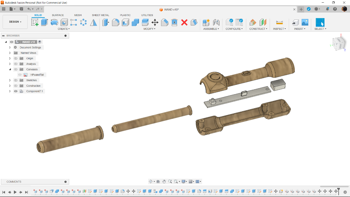
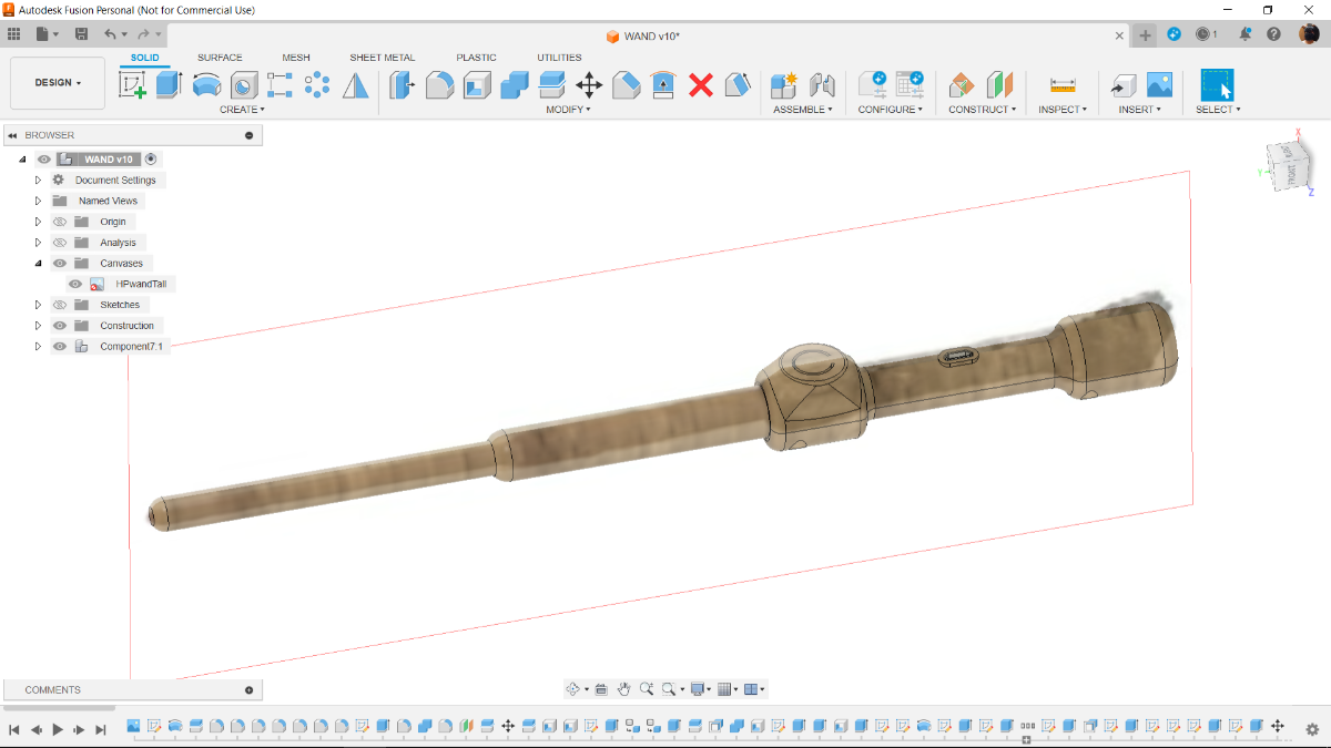
The first step in the design process was to import an image of a wand into Fusion360 from the internet.
We calibrated the length of the wand, to be exact, 300mm. Next, the calibrated image will be traced to create a rudimentary sketch, which will subsequently be used to create a rough body.
The idea was to stick to the basic wand shape rather than trying to replicate the asymmetrical details or wood texture, which would be difficult to print on my Ender 3 printer.
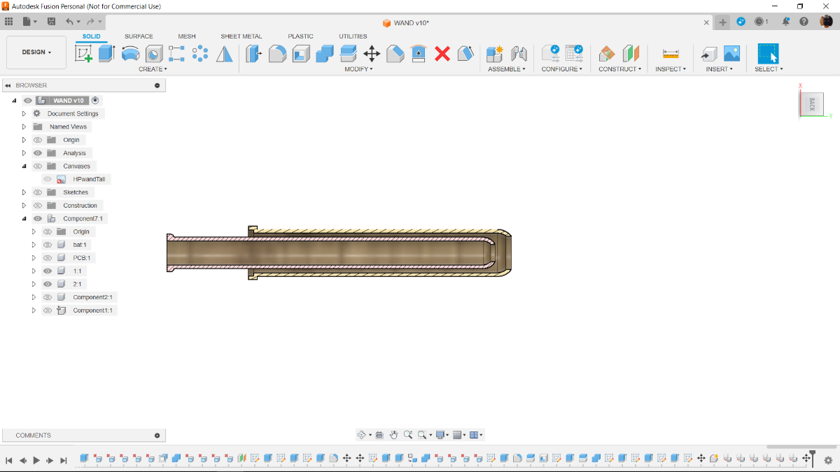
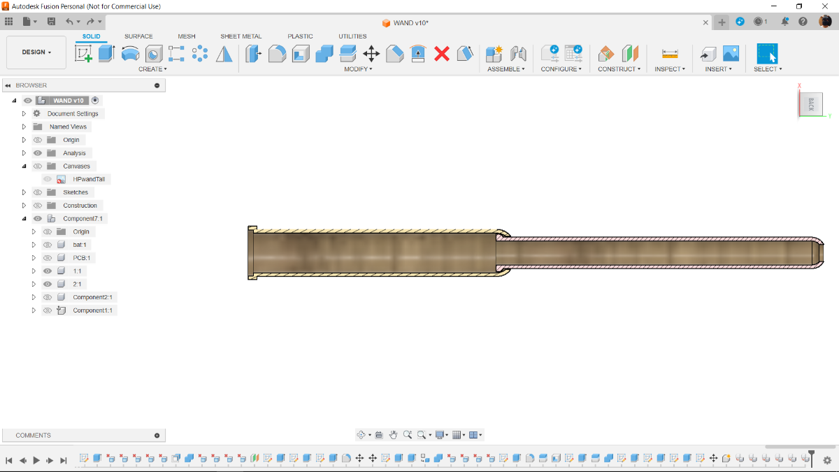
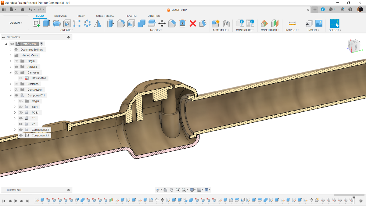
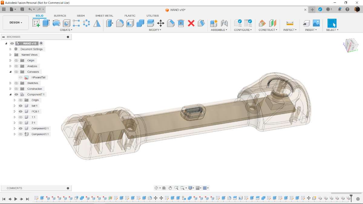
With the intention of incorporating a torch light within the wand, we hollowed out the design and separated it into three sections: the handle, the upper shaft, and the lower shaft.
The handle portion has the upper and lower shaft sections attached in place and mounted together.
A little LiPo cell is positioned inside the handle's lower portion, and we have put a circuit inside the handle portion that will house all the electronics.
The handle portion is split into two halves.
On the handle portion, we have also incorporated a switch knob.
3D Parts


Once the model was complete, we used a 0.4mm nozzle, 20% infill, and 0.2mm layer height to 3D print each component out of brown PLA.
The process of assembling the upper and lower shafts involves inserting the upper shaft through the lower shaft and securing it with superglue.
Circuit
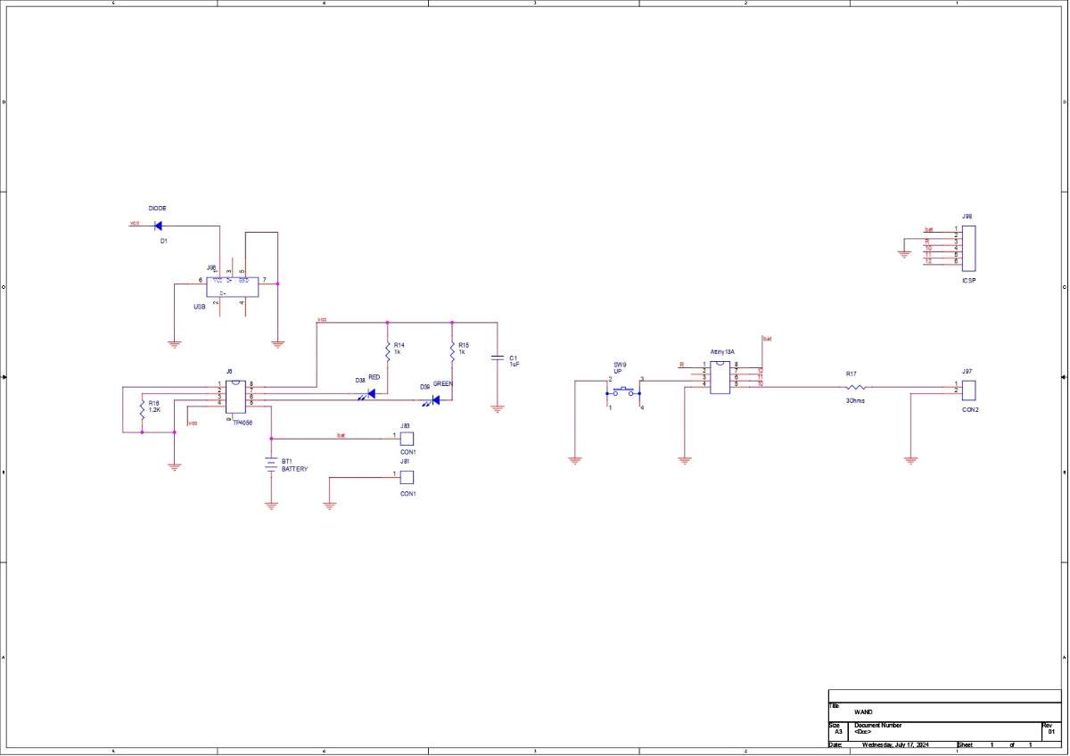

In this instance, an Attiny13A 8-bit MCU is connected to a switch on pin 4, and a load resistance is used to control current by connecting the LED load directly to pin 0.
We are using a LiPo cell as our power source, and it is coupled to a separate charging IC arrangement that includes a TP4056 minimal setup.
Also, we will be using a vertical USB Micro Port here for charging input for the TP4056 IC.
As for the LED, we are using a 5mm white LED made by EVERLIGHT.
With a forward voltage of 2.8V to 3.6V, this high-luminous white LED is commonly utilized in torch lighting applications. Its 15 degree viewing angle and maximum forward current of 30 milliamperes make it ideal for our Wand-Flashlight project.
https://en.everlight.com/visible_led/category-lamp_led/5mm_round_type__333/
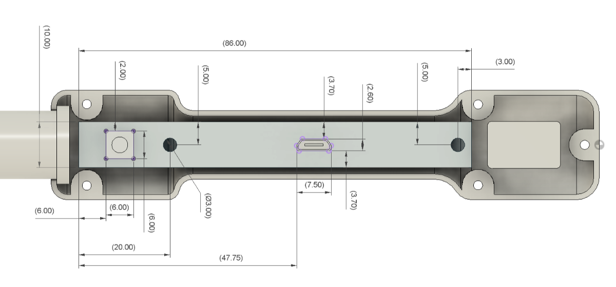
We used measurements from the cad design to prepare the PCB, which included the position of mounting holes and Switch.
PCB Assembly Process
- The PCB assembly process started by first adding solder paste to each component pad using a solder paste dispensing needle.
- Next, we pick and place all the SMD components in their place using an ESD Tweezer.
- We place the circuit on our DIY SMD REFLOW HOTPLATE, which heats the PCB from below up to the solder paste melting temperature, and components are soldered to their pads.
- We then added the vertical USB port and Push Switch to their locations and soldered their pads using a soldering iron.
Power Source: LiPo Cell
- Once the circuit was finished, we connected the battery connectors of the circuit to the positive and negative terminals of the LiPo cell.
- After that, we plug in the power via the USB port and measure the current drawn—0.23 A—using a USB power meter. As the battery charges, the current it draws will decrease. At the moment, the battery's voltage is 3.8V, and its maximum voltage will be 4.2V.
- The red LED will glow during the charging process; however, the green LED will turn on and the red LED will switch off when the battery reaches 4.2V.
Flashing the Attiny 13A
As for the brain of this project, we used Attiny13A here, which will be programmed using our previously made Arduino as an ISP shield.
Multiple Attiny85 Or 13a Programmer (electronicwings.com)
Here, we added the circuit to the programming shield by placing the programming CON6 header pins with the CON6 header pins of the mainboard.
- Next, we install the Attiny13 Core files for Arduino by going to the below link.
https://github.com/MCUdude/MicroCore
- After installing and setting up the core files, we go to the tool menu and select the Attiny13 on board. We set the B.O.D to 1.8V and selected the programmer as "Arduino as ISP.".
- We then burn the bootloader, which takes up to 30 seconds to burn.
- Once the bootloader has been burned, we select "Upload using programmer" from the sketch menu to upload the sketch to Attiny13. The ISP flashing method does not support the regular upload method.
MAIN CODE
Here's the code used in this project.
const int switchPin = 4;
const int lightPin = 0;
int lightMode = 1;

void setup()
{
    pinMode(lightPin, OUTPUT);
    pinMode(switchPin, INPUT_PULLUP);
    digitalWrite(lightPin, LOW);

}
void loop()
{
    if (digitalRead(switchPin) ==LOW)
    {
        lightMode = lightMode + 1;
        if (lightMode == 4)
        {
            lightMode = 1;
        }
    }
    if (lightMode == 1)
    {
        digitalWrite(lightPin, 50);
        delay(500);
    }
    else if (lightMode == 2)
    {
         analogWrite(lightPin, 250);
        delay(500);
    }
    else if (lightMode == 3)
    {
        analogWrite(lightPin, LOW);
        delay(500);
    }
    //delay(200); // see text
}
Wand Assembly Process
- The first step in the main assembly procedure is to attach two 190mm wires to the 5mm LED's positive and negative terminals.
- The 5mm LED was then pushed inside the shaft assembly, causing the LED to pop out from the shaft's end.
- With the help of superglue, we secure the LED in its place.
- We now connect the LED terminals to the load terminals, or CON2 pads, which are on the main PCB.
- The circuit is then placed on top of the designated screw bosses, and the battery is then placed in its proper position on the other end of the handle.
- In order to secure the circuit in place, we join it with the handle portion screw bosses using two M2 screws.
- The shaft assembly is then placed on the handle part, and the shaft's position is held in place by the other handle part. These two components will ensure that the shaft assembly remains in place.
- We use five M2 screws to mount both handle parts together.
The assembly is now complete.
RESULT
Here's the result of this magical build: a working Wand-Flashlight that works.
The light is controlled by a switch on the grip of the wand. Here, a white, 5mm Everlight LED with a 15-degree viewing angle provides the light; in the past, torches used these LEDs.
Although this wand cannot be used for magic, the Attiny13 that is being used here is doing a wonderful job of driving the LED.
This Wand-Flashlight can be used outside without any issues as a test. Although it is not very bright, the light works. In the upcoming version, a high power SMD LED will replace the 5mm LED to improve lighting.
Overall, this project was a success, but I will be preparing version 2 to improve the light intensity.
Thanks for reaching this far, and I will be back with a new project pretty soon.
Peace.