Watch the video for a better tutorial.
Attiny MCUs are very popular as it is quite easy to program them and using them instead of the atmega328 chip can reduce the cost of the overall project which requires less input/outputs.
So let me show you guys how to make a Programmer for these Attiny chips in order to flash them like a pro.
6 Attiny in parallel at the same time!
Designing a Programming Shield
STEP 1 - Designing the PCB
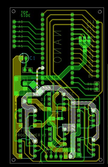
I designed this nano breakout board in OrCad Cadance, it has four LEDs (3 of them are connected to D7 D8 and D9 for ICSP programming status, and the fourth one is connected to D11 or D0 of attiny in case we need to test attiny onboard)
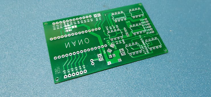
I send it to a PCBWAY and got PCBs in 22 days (because of the pandemic situation)
STEP 2 - ASSEMBLY!
We just need the following things for this project-
Arduino nano x1
DIP8 Sockets x6
1uf 10V CAP x1
male headers 28 to be exact
LEDs 0603 package x4
1K Resistor 0805 package x2
PCB
3D printed enclosure
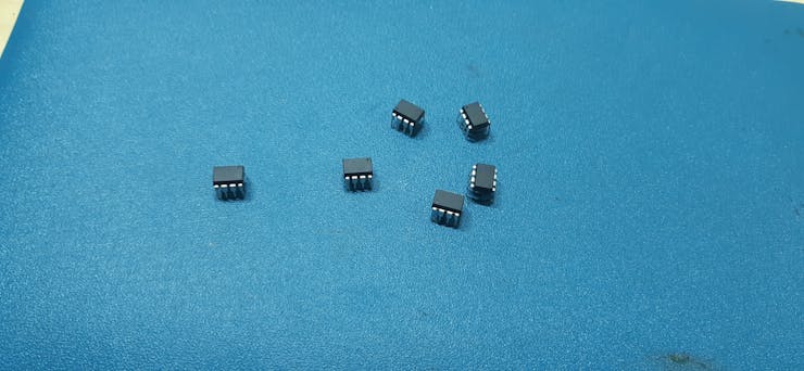
attiny85 x6
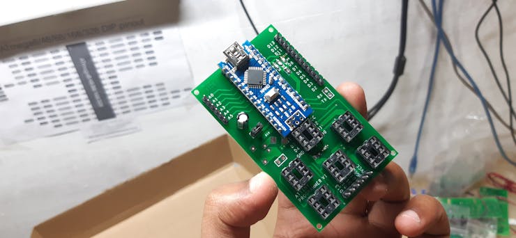
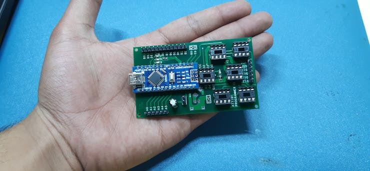
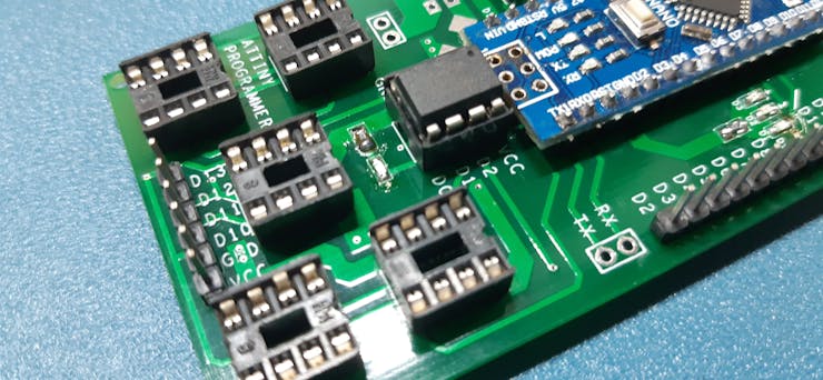
after gathering the above components, I just solder them all together and made this slick-looking Programmer.
STEP 3 - Testing
first, I plugged the Arduino nano with my computer and flashed it with a simple Chaser led sketch which will toggle led connected to pin D7, 8, 9, and D11 in chaser order. left to right
After this, I uploaded "Arduino as ISP" sketch from example sketches to this board and shorted the jumper after the sketched was uploaded.
I plugged out the USB cable and bring out 6 attiny85, for programming.
STEP 4 - Getting the Core files and Programming the ATTINY85/13A
now before programming the attiny85, we need to get its core from here- https://github.com/SpenceKonde/ATTinyCore
(just follow the installation process which is very thorough and simple)
after installing the core files, placed ATTINY in dip sockets carefully without applying too much pressure because guess what,
if you apply too much force, ATTINY legs will bend,
Now open Blink sketch or any other sketch that you want to flash it onto your attiny (I'm gonna flash blink sketch and output pin is D0)
#1
plug your attiny on DIP socket and get ready for programming,
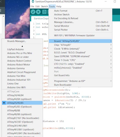
select the right MCU which is attiny85 in our case, and do not forget to choose the right com port.
#2
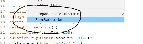
HIT BURN BOOTLOADER and wait for a few moments.
#3
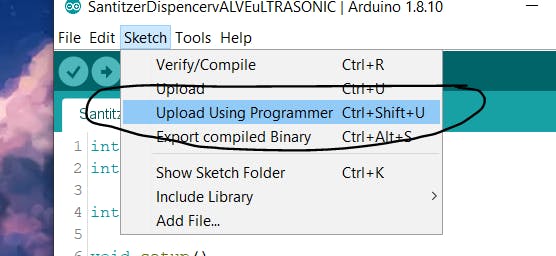
hit UPLOAD VIA Programmer
and bang, you have successfully programmed multiple tiny at the same time,
here's the result.
put them on a breadboard and connect led with D4* and GND and power them separately.
with this setup, you can program more than 1 attiny at the same time which is quite a useful feat, as you can now replicate your project at ease or you can even produce them for selling applications.
I hope this post was helpful in some way. everything here is OPENSOURCE so if you need something, just leave a comment.