
ZeroDesk: An Open-Source Arduino DAW Controller for Creators Who Cannot Afford to Be Locked Out Making Professional Music Production Hardware Accessible to Everyone
Music production is one of the most powerful forms of human expression, yet the hardware that makes it professional is priced out of reach for the majority of the world's creators. A DAW controller — the physical device that gives producers hands-on control over their digital audio workstation costs between $150 and $600. And for creators in developing economies, that price tag is only half the problem. Import costs, limited local supply, and distribution gaps turn equipment that is routine in western markets into something that feels completely out of reach everywhere else.
ZeroDesk was built to change that.
What Makes ZeroDesk Different?
ZeroDesk is a fully open-source DAW control surface built on the Arduino Uno for under $15 in components. It gives music producers, podcasters, and audio engineers real-time hardware control over any major Digital Audio Workstation — including Reaper, Ableton Live, Logic Pro, Cakewalk by Bandlab, and Cubase — through four smooth analog faders, dedicated transport buttons, and a live OLED mixer display.
Unlike commercial controllers that lock users into proprietary ecosystems, expensive drivers, and subscription software, ZeroDesk transmits standard MIDI protocol over serial communication — making it universally compatible with every DAW on Windows, macOS, and Linux. No proprietary drivers. No subscriptions. No ecosystem lock-in. Just open hardware that works.
The firmware runs an 8-sample rolling average filter on every analog input, delivering studio-grade fader smoothness that rivals hardware costing 20 times more. The live OLED mixer display updates at 10 frames per second, giving the engineer a real-time visual readout of their session. And because every design decision from the deadband threshold to the display refresh rate — is documented and open, anyone in the world can build it, modify it, and improve it.
Why It Matters
- Accessibility — Professional DAW control for under $15, removing the financial barrier that excludes the majority of the world's music creators
- Geography — Designed and built in Nigeria, where import costs and limited supply make commercial studio hardware largely inaccessible
- Open Source — Every line of firmware, every wiring diagram, and every design decision is freely available for anyone facing the same wall to build their own
- Community — ZeroDesk is not just one device. It is a foundation. Every version released will remain open, so the global maker and music production community can build on it together
- Education — ZeroDesk demonstrates that MIDI protocol, analog signal conditioning, and real-time firmware design are accessible skills that any engineer can learn and apply to solve real problems
The Bigger Picture
ZeroDesk is not just a hardware project. It is a statement about who gets to participate in professional creative technology. The tools to produce, record, and mix music should not be determined by where you were born or what you can afford to import. By combining open-source firmware, accessible components, and a clear build guide, ZeroDesk puts professional studio control in the hands of every creator on the planet, regardless of budget or geography.
This is Version 1.0. A working prototype and the beginning of a growing open platform. Future versions will add more channels, wireless MIDI, and expanded DAW integration — all open, all free, all built for the creator who cannot afford to be locked out.
Components
- 1x Arduino Uno — Central microcontroller
- 1x 0.96" I2C OLED Display (SSD1306)
- 4x 10K Slide Potentiometer
- 3x Momentary Push Button
- 1x USB Type-B Female port
- Jumper Wires
- Breadboard and perfboard
.png)
Tools
- Arduino IDE (free) — for writing and uploading firmware
- Hairless MIDI (free) — for bridging serial to MIDI
- loopMIDI (free, Windows only) — for creating a virtual MIDI port
- Soldering Kit (iron, solder wire, flux, wick) — for permanent assembly
- Screwdriver Kit — for enclosure assembly
- Drill — for cutting enclosure holes for buttons
- Angle grinder- for cutting enclosure holes for the slide potentiometer, and OLED window
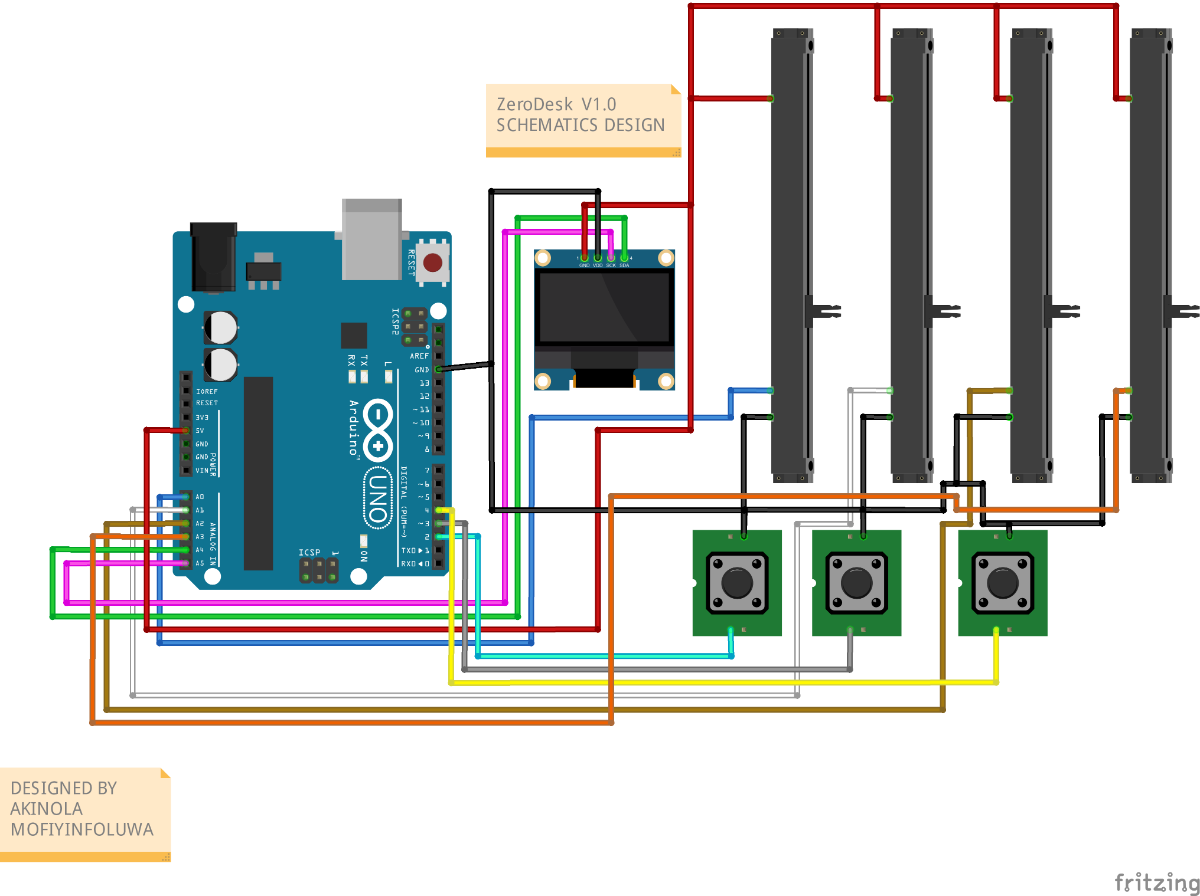
Step 1: Circuit schematic design
Designing the ZeroDesk schematic was the very first milestone in this project.
Before touching a single wire, I mapped out the full circuit to understand exactly how every component would connect to the Arduino Uno and how the signal would flow from physical input to MIDI output. The goal was to keep the schematic as clean and minimal as possible — no unnecessary components, no complexity that would make the build harder to reproduce.
The schematic integrates four key elements:
- Arduino Uno as the central microcontroller and MIDI transmitter
- 0.96" I2C OLED Display connected on the I2C bus via pins A4 (SDA) and A5 (SCL)
- Four 10K potentiometers connected to analog inputs A0 through A3 as channel faders
- Three momentary push buttons on digital pins 2, 3, and 4 wired directly to GND, using the Arduino Uno's internal pull-up resistors — eliminating the need for any external resistors entirely
What made this schematic powerful was its deliberate simplicity. Every component connects directly to the Arduino Uno with no additional ICs, no shift registers, and no external passive components beyond the potentiometers themselves. This keeps the build reproducible by anyone with basic electronics knowledge and a breadboard, while still delivering a fully functional professional tool.
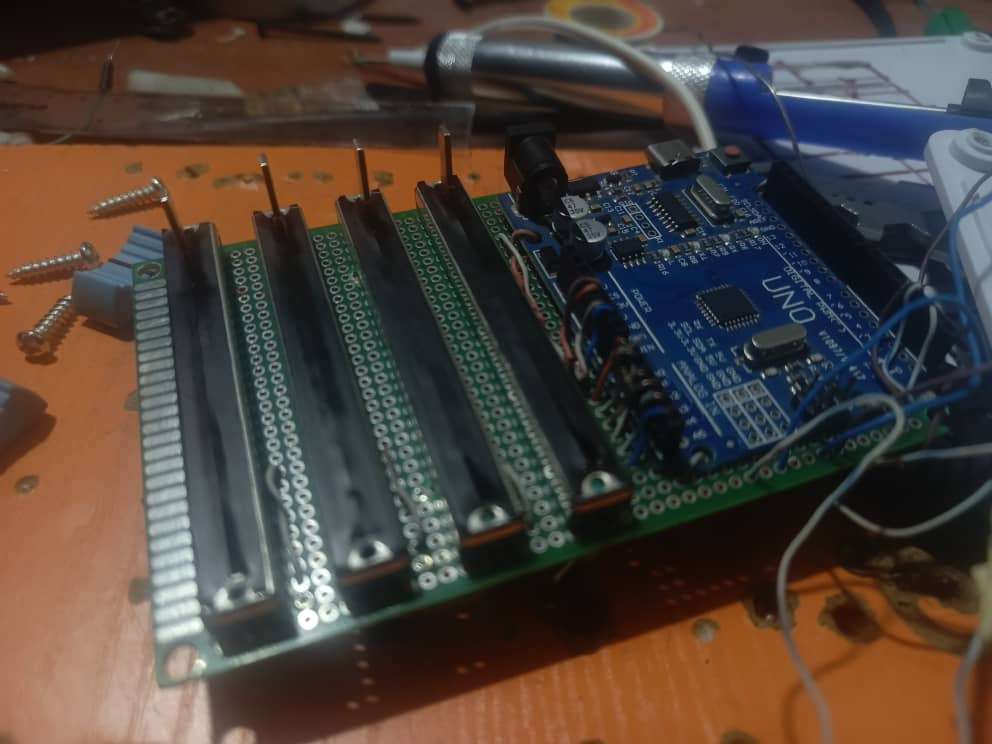
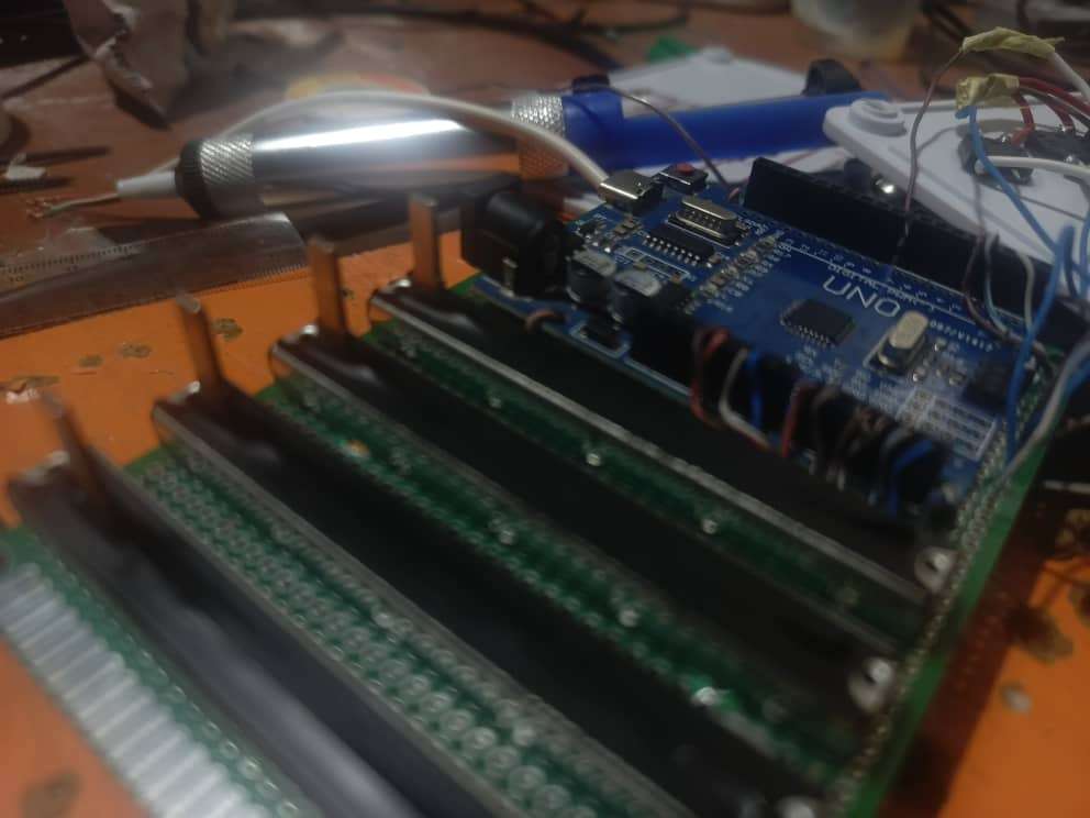
Step 2: Wiring the Circuit
With the schematic finalised, the next step was bringing it to life on a breadboard. Working from the schematic, I wired every component to the Arduino Uno one section at a time — starting with the OLED display, then the potentiometers, and finally the buttons — testing each connection before moving to the next. This staged approach made debugging significantly easier and ensured that by the time all components were connected, each section was already independently verified.
Wiring the OLED Display
The first component to go in was the OLED display. Because it uses I2C communication, it only needs four wires to the Arduino Uno — making it the cleanest connection in the entire build. GND connects to GND, VCC connects to 5V, SDA connects to A4, and SCL connects to A5. Once wired, I uploaded a quick I2C scanner sketch to confirm the display was being detected at address 0x3C before moving forward. Seeing that address appear in the serial monitor confirmed the display was wired correctly and ready for the firmware. Below is a code test if you Oled is wired correctly
#include <Wire.h>
void setup() {
 Wire.begin();
 Serial.begin(115200);
 Serial.println("Scanning I2C...");
}
void loop() {
 for (byte address = 1; address < 127; address++) {
   Wire.beginTransmission(address);
   if (Wire.endTransmission() == 0) {
     Serial.print("Device found at 0x");
     Serial.println(address, HEX);
   }
 }
 delay(5000);
}
Upload the above sketch and open Serial Monitor. If you see 0x3C — your OLED is wired correctly
Wiring the Potentiometers
With the display confirmed, the four potentiometers went in next. Each potentiometer has three pins and the wiring logic is identical for all four. The left pin connects to GND, the right pin connects to 5V, and the middle pin — the wiper — carries the analog signal. The four wipers connect to A0, A1, A2, and A3 on the Arduino Uno respectively, giving four completely independent analog fader readings. To verify each connection, I used a simple analogRead sketch in Arduino IDE and confirmed that each pot returned a smooth 0 to 1023 range as it was turned from one end to the other. Any reading that jumped erratically indicated a loose connection that needed reseating before continuing. Below is a code test if you each potentiometer is working and wired correctly
void setup() {
  Serial.begin(115200);
}

void loop() {
  Serial.print("P1:"); Serial.print(analogRead(A0));
  Serial.print(" P2:"); Serial.print(analogRead(A1));
  Serial.print(" P3:"); Serial.print(analogRead(A2));
  Serial.print(" P4:"); Serial.println(analogRead(A3));
  delay(100);
}
Open Serial Monitor and turn each pot. Each should return a smooth 0–1023 range with no jumping.

Wiring the Buttons
The three transport buttons were the simplest part of the entire wiring stage. Each button has two legs. One leg connects to a digital pin — pin 2 for Play, pin 3 for Stop, and pin 4 for Record. The other leg connects directly to GND. No external resistors are needed at any point because the Arduino Uno's internal pull-up resistors are activated in the firmware using INPUT_PULLUP mode. This keeps the circuit clean, reduces component count, and eliminates one of the most common beginner mistakes — forgetting a pull-down resistor and getting erratic button readings. To test each button before uploading the full firmware, I used a simple digitalRead sketch and confirmed that each pin read HIGH at rest and LOW when the button was pressed. Below is a code test if you each button is working and wired correctly
void setup() {
  pinMode(2, INPUT_PULLUP);
  pinMode(3, INPUT_PULLUP);
  pinMode(4, INPUT_PULLUP);
  Serial.begin(115200);
}

void loop() {
  Serial.print("Play:"); Serial.print(digitalRead(2));
  Serial.print(" Stop:"); Serial.print(digitalRead(3));
  Serial.print(" Rec:"); Serial.println(digitalRead(4));
  delay(100);
}
Each button should read 1 at rest and 0 when pressed. If any button reads 0 constantly, check the wiring on that pin.
Step 3: Firmware
With the circuit fully wired and tested, the next step was writing and uploading the firmware that brings ZeroDesk to life. This is where the hardware becomes a musical instrument.
Installing the Libraries
Before writing a single line of code, two libraries need to be installed in Arduino IDE. The OLED display requires the Adafruit SSD1306 library and its dependency, Adafruit GFX. Both are available directly through the built-in Library Manager under Sketch → Include Library → Manage Libraries. Search each name, click Install, and accept any dependency prompts. Without these two libraries the display will not initialise and the firmware will not compile.
Understanding the Firmware
The ZeroDesk firmware is built around a single continuous polling loop that runs four parallel tasks on every cycle — reading the potentiometers, checking the buttons, transmitting MIDI data, and updating the OLED display. Every design decision in the firmware was made with one priority in mind: hardware control must always be fast, smooth, and reliable.
The four key firmware systems are:
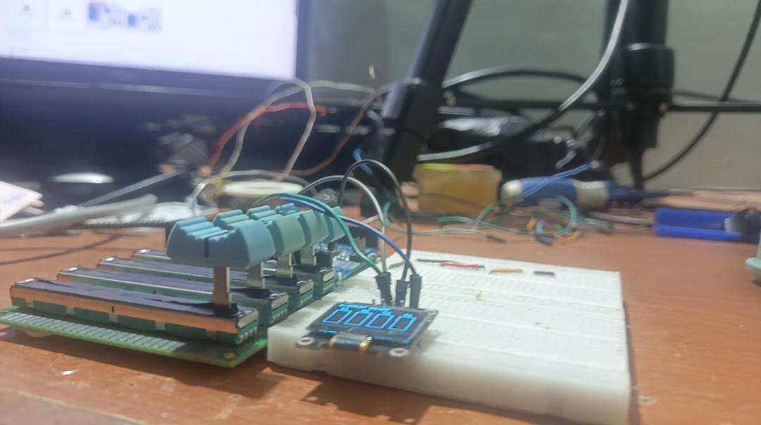
Startup Screen
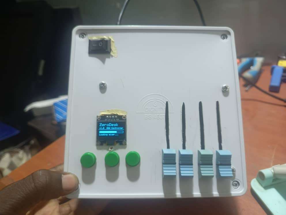
The very first thing ZeroDesk does on power-up is display its identity. The OLED shows the ZeroDesk v1.0 name and version with an animated loading bar that fills across the screen over three seconds before the live mixer view loads. This was a deliberate product design decision — a device that introduces itself feels finished. A device that just boots into a blank screen does not.
.jpeg)
8-Sample Rolling Average Smoothing Raw analog readings from potentiometers are inherently noisy. Every ADC read on the Arduino Uno picks up small amounts of electrical interference that causes the MIDI value to jump erratically — even when the knob is not being touched. Left unaddressed, this floods the DAW with hundreds of redundant MIDI messages per second and causes faders to twitch in the software.
The solution is an 8-sample rolling average filter on every analog input. Instead of transmitting the raw reading, the firmware maintains a buffer of the last 8 readings per channel and transmits the average. This smooths out noise entirely without introducing any noticeable lag. On top of this, a deadband threshold of 2 MIDI steps means a new message is only transmitted when the value has genuinely changed by at least 2 steps — preventing redundant messages from ever reaching the DAW. The result is studio-grade fader smoothness that is indistinguishable from hardware costing 20 times more.
Transport Button Handling Each button is read using edge detection — the firmware compares the current state to the previous state on every loop cycle and only fires a MIDI message when the state actually changes. This ensures clean single-press events with no double-firing. A 15ms debounce delay absorbs the mechanical bounce that occurs in every physical button the moment it is pressed or released. The firmware sends a MIDI Note On message when the button is pressed and a MIDI Note Off message when it is released — exactly matching the behaviour that DAW MIDI learn systems expect.
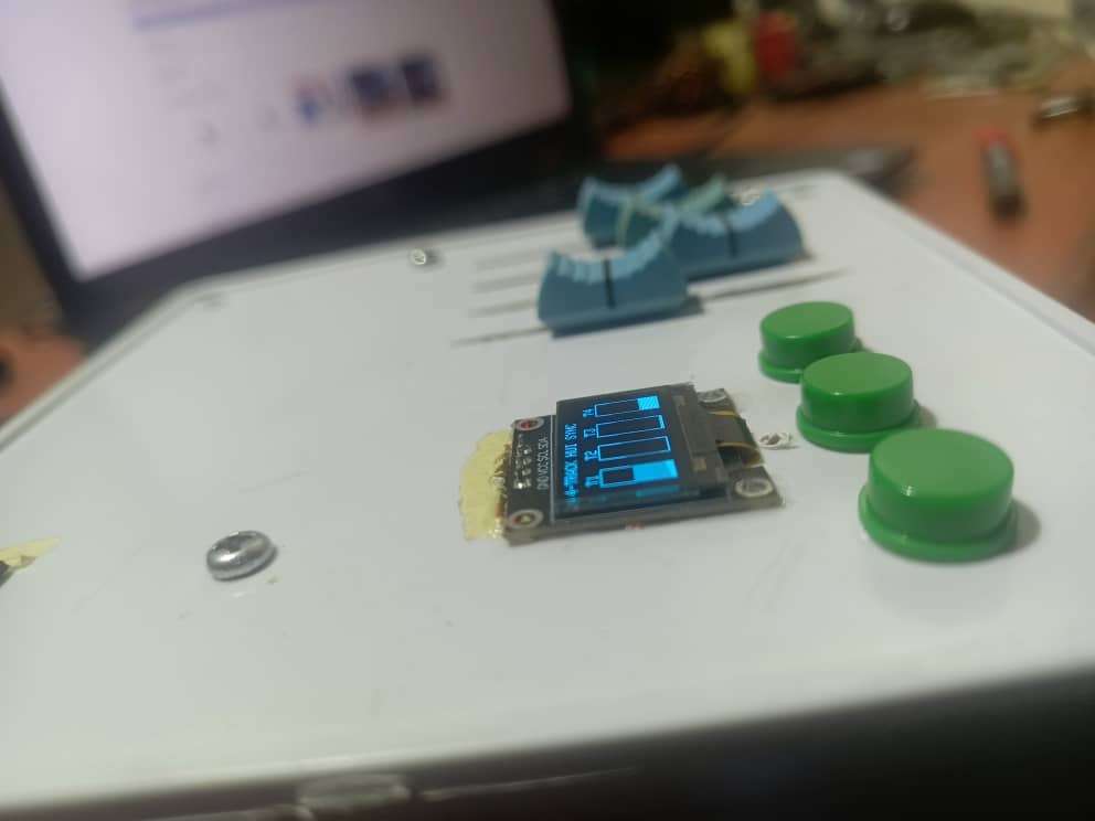
Rate-Limited OLED Rendering The OLED display updates at exactly 10 frames per second — once every 100 milliseconds. This rate was chosen carefully. Fast enough that the volume bars appear fluid and responsive. Slow enough that the display update never blocks or delays the input polling loop. The display logic is completely decoupled from the control loop using a millisecond timer, meaning the fader and button responsiveness is never sacrificed for a visual update. Hardware control always takes priority.
Uploading the Firmware
With the libraries installed, open the ZeroDesk v1.0 sketch in Arduino IDE. The full firmware can be found in the code section
Connect the Arduino Uno to the PC via USB. Under Tools → Board, select Arduino Uno. Under Tools → Port, select the correct COM port — the same one that appears when the board is connected. Click Upload.
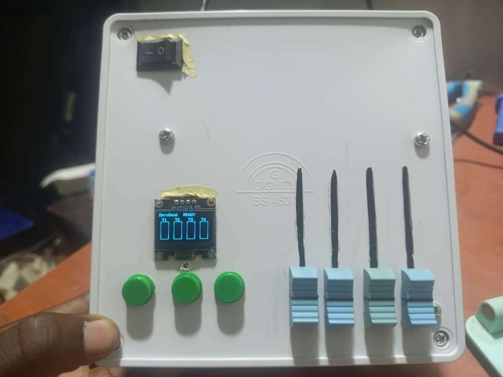
The moment the upload completes, the OLED will light up with the ZeroDesk startup screen. The animated loading bar will count up to ready and the live mixer view will load. If that screen appears, the firmware is running correctly and every component is wired as expected.
.jpeg)
Conclusion
ZeroDesk v1.0 started as a personal frustration and became something bigger than I expected. The goal was simple — build the studio tool I could not afford to buy. What came out the other side was a fully functional, open-source DAW controller that works with any major DAW, costs under $15, and can be built by anyone with basic electronics knowledge and a few hours to spare.
Every decision in this project — from choosing the Arduino Uno as the core platform, to the 8-sample smoothing algorithm, to the rate-limited OLED rendering was made with one principle in mind: it has to actually work. Not work on a bench under ideal conditions, but work in a real session, on a real track, with a real Sound engineer relying on it.
The bigger lesson ZeroDesk taught me is that the gap between what professional hardware costs and what it actually takes to build is enormous. That gap exists not because the technology is complex, but because the knowledge of how to close it is not evenly distributed. Open-source projects like this one exist to close that gap one build at a time.
This is Version 1.0. The foundation is solid, the mission is clear, and the roadmap is already written. If you build ZeroDesk, improve it, or take it in a direction I have not thought of yet — share it. That is the entire point.
The studio should belong to everyone.