
Video
DigiKey My List
Introduction
Hello! We are Vedant, Abhishek and Amey, and we are thrilled to launch the internet's first-ever end-to-end tutorial on Automation 4.0. Aspects like digital twin and AR
Most tutorials stop at basic IoT or simple robotics. We are going further. We are building a complete, industrial-grade ecosystem that bridges the gap between physical hardware, edge intelligence, and immersive visualization.
In this , you will learn how to implement core Industry 4.0 concepts—specifically Digital Twins and Augmented Reality (AR) systems—from the ground up.
A Digital Twin is a real-time virtual counterpart of a physical object or process. It is not just a static 3D model. It is a live simulation that receives continuous data streams (position, velocity, torque) from the physical robot. It allows operators to monitor performance, predict maintenance needs, and simulate operational changes in a safe virtual environment before applying them to the real hardware.
Augmented Reality bridges the physical and digital worlds by overlaying virtual information onto real-world objects.AR allows engineers to look at a machine (via a tablet or headset) and see live diagnostics—such as temperature heat maps, joint angles, or error codes—floating directly over the components .Drastically reduces maintenance time and improves operator situational awareness.
Our entire tutorial is divided into three distinct phases, mirroring a real-world industrial deployment pipeline.:
Phase 1: The Hardware (6 DoF Robotic Arm)
Develop a 6 Degrees of Freedom (6 DoF) robotic arm. This arm will serve as our demo for "actual industrial hardware," giving us a complex physical system to monitor
Phase 2: The Edge Layer (ESP32 & RS485)
Build the intelligence layer using an ESP32.The ESP32 will tap into the robot's RS485 communication line to sniff data packets.Instead of just sending raw data, the ESP32 will perform Edge Fault Detection locally in real-time.Processed data and health status are sent to the cloud instantly via HTTP.
Phase 3: The Application Layer (Unity, Digital Twin & AR)
Create the user interface and backend using Unity.A robust system to receive the real-time data stream from the ESP32. A desktop/mobile view where the 3D robot moves in perfect sync with the physical robot.An augmented reality experience that visualizes the robot's internal data when pointing a camera at the physical arm.
Now let's breakdown each phase in detail:-
Phase 1: The Hardware (6 DoF Robotic Arm)
We Start from 3d printing all the 12 3d components and using the video below for assembly https://www.youtube.com/watch?v=K7cXGwFUkkY . Thanks to omartronics.com for providing the open source robotic arm for the tutorial.
.png)
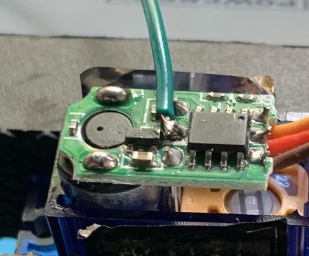
- Standard hobby servos are "open-loop" systems from the perspective of the controller—you tell them to go to 90 degrees, but they don't tell you if they actually arrived or if they were forced out of position.
For a Digital Twin, we need to know the exact real-world position of the arm at all times. To do this, we "hack" the servos to expose their internal potentiometer (voltage divider).
Steps to Convert to "Feedback Servos":
- Open the Servo: Unscrew the four screws at the bottom of the MG995/SG90.
- Locate the Potentiometer: You will see three wires connected to a potentiometer inside.
- Solder the Feedback Wire: Solder a new wire (preferably a different color, like yellow or white) to the middle pin (wiper) of the potentiometer.
- Reassemble: Route the wire out of the case and screw the bottom back on.
.png)
3.Than we go and wire up the entire assembly to arduino nano as per the schematic shown below
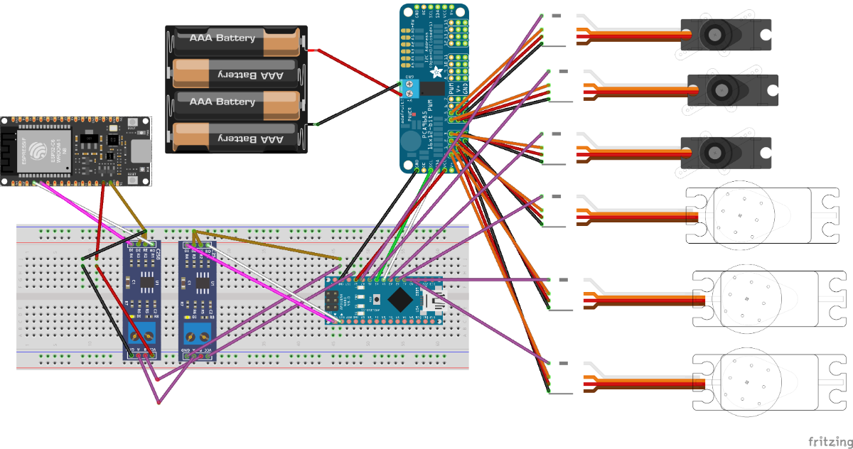
Wiring Connection Guide
1. Power Supply & Common Ground
- Battery (+) Red → PCA9685 Terminal (+)
- Battery (-) Black → PCA9685 Terminal (-)
2. Logic Level Converter (LLC) Wiring Voltage Reference:
- ESP32 3.3V → LLC LV (Low Voltage)
- Arduino 5V → LLC HV (High Voltage)
- GND → LLC GND
Data Transmission (ESP32 to Arduino):
- ESP32 TX → LLC LV1 → LLC HV1 → Arduino RX (D0)
Data Reception (Arduino to ESP32):
- Arduino TX (D1) → LLC HV2 → LLC LV2 → ESP32 RX
3. Servo Driver (PCA9685) to Arduino
- Arduino 5V → PCA9685 VCC
- Arduino GND → PCA9685 GND
- Arduino A4 (SDA) → PCA9685 SDA
- Arduino A5 (SCL) → PCA9685 SCL
4. Servo Feedback (Position Sensing) Connect the extra "feedback wire" from each servo to the Arduino Analog pins:
- Servo 1 (Base) → Arduino A0
- Servo 2 (Shoulder) → Arduino A1
- Servo 3 (Elbow) → Arduino A2
- Servo 4 (Wrist Pitch) → Arduino A3
- Servo 5 (Wrist Roll) → Arduino A6
- Servo 6 (Gripper) → Arduino A7
5.Upload code Last we will upload the nano_transmit_code_ino to arduino nano which will run a basic pick and place code , also capture the target servo and actual servo ( potentiometer feedback ) and send the 2 arrays in the form [s0,s1,s2,s3,s4,s5,s6] to esp32 via rs485.
Phase 2 :The Edge Layer
We start by creating a fire base account
- Click on create a new Firebase project , enter your project name , yes to all options
.png)
2. You’ll be redirected to your Project console page.
.png)
3..On the left sidebar, click on Build > Authentication and then on Get started >Select Email/Password and enable that authentication method. Then, click Save.
.png)
4. Add your email and password that you have entered in your esp32 code -

5.Creating a Realtime Database > On the left sidebar click on Build > Realtime Database and then, click on Create Database
.png)
6.Select database location as Singapore > Select Test mode
.png)
7.Your database is now created. You need to copy and save the database URL—highlighted in the following image—because you’ll need it later in your ESP32 code.
.png)
8.Get project api -To get your project’s API key, on the left sidebar click on Project Setting > Copy the API Key to the esp323 code
.png)
9. Upload the esp32 code after changing your credentials to it
File name - esp32_recieve_code
Esp32 code summary -
- Secure Authentication: The code initializes a UserAuth object using your specific Email and Password, creating a secure, persistent connection to Google Firebase without using insecure "database secrets."
- Binary Data Ingestion: Instead of reading slow text, the uartTryReadPacketAndParse function waits for a specific Header (0xAA) and reads exactly 50 bytes of raw binary data from the RS485 bus.
- Data Reconstruction: It uses memcpy (memory copy) to instantly convert the raw byte stream back into two arrays of 6 floats (targetAngle and actualAngle). This is the fastest possible way to process data.
- Signal Integrity Check: Before processing, it calculates a Checksum (XOR sum) of the received data. If the calculated sum doesn't match the received checksum byte, the packet is discarded as noise.
- Edge Intelligence (The "Brain"): The checkErrors function runs continuously. It compares the Target vs. Actual positions and calculates velocity (delta).
- Fault Classification: It assigns specific error codes based on logic:
- ERR_STALL (2): Motor wants to move (error exists) but hasn't moved physically for 400ms.
- ERR_NOISE (4): Position jumped impossibly fast (e.g., >10 degrees in one loop).
- ERR_RANGE (5): Sensor value is outside physical limits (0-300).
- Cloud Synchronization: Every 500ms (sendInterval), it converts the processed arrays into JSON-formatted strings ("[90, 45, ...]") and uploads them to Firebase. This formatting ensures the Unity app (Phase 3) can easily read the data.
Phase 3 : The Application Layer (Unity, Digital Twin & AR)
If you find Unity to be overwhelming we have provided you with the installation files of our application. Install them and you can directly monitor our robot.
https://github.com/abhishek2935/AR-and-DigiTwin-App-distribution
Look for our updates , it will allow you to import your own model and database in the app to be monitored.
Install Requirements
- Unity Hub
- Unity 2021+ (recommended 2021.3 LTS or newer)
- Firebase Unity SDK
- A Firebase project with Realtime Database
- A Windows PC
Create and Configure the Firebase Project
- Go to Firebase Console
- Create a new project.
- Enable Realtime Database.
- Set rules to allow read/write (or authenticated rules as needed).
- Add a Unity app inside Firebase (NOT Android).
- Download the Firebase config files for Windows/Desktop: google-services-desktop.json
- Place the file inside Unity at: Assets/
Setup the Unity Project
- Open Unity Hub → Create a new 3D Unity Project.
- In the Unity project:
- Assets/Scripts
- Assets/Models
- Assets/Prefabs
- Assets/StreamingAssets (place Firebase config here)
- Import:
- Firebase → FirebaseDatabase.unitypackage
- Unity will ask to resolve dependencies → Click Resolve.
Import the Robot Arm Model
- Drag the robotic arm FBX file into Assets/Models.
- Open it in the scene.
Create a clean hierarchy:
Base
└── Joint1
└── Joint2
└── Joint3
└── Joint4
- Adjust pivot points correctly for each joint axis.
- Turn this into a Prefab
5. Create the Firebase Reader Script
Create script: FirebaseReader.cs
This script should:
- Connect to Firebase
- Read joint angles from Realtime Database
- Store them in a public float array
Typical structure:
public class FirebaseReader : MonoBehaviour
{
    public float[] actualValues;
    void Start()
    {
        FirebaseDatabase.DefaultInstance
        .GetReference("robot")
        .ValueChanged += (sender, e) =>
        {
            if (e.Snapshot.Exists)
            {
                actualValues = JsonUtility.FromJson<AngleData>(e.Snapshot.GetRawJsonValue()).values;
            }
        };
    }
}

[System.Serializable]
public class AngleData
{
    public float[] values;
}

Database expected structure:
robot: {
  values: [30, 45, 10, 90]
}
Create the Joint Controller Script
Create script: RobotJointController.cs
This script:
- Reads actualValues from FirebaseReader
- Rotates joints accordingly
public class RobotJointController : MonoBehaviour
{
    public Transform[] joints;
    public FirebaseReader reader;

    void Update()
    {
        if (reader.actualValues == null) return;

        for (int i = 0; i < joints.Length; i++)
        {
            joints[i].localRotation = Quaternion.Euler(
                0,
                reader.actualValues[i],
                0
            );
        }
    }
}
Connect Everything in the Unity Scene
- Drag your robot prefab into the scene.
- Add FirebaseReader to an empty GameObject.
- Add RobotJointController to the arm root.
- Assign:
- The 4 joints in the Inspector
- The FirebaseReader to the controller
- Save scene.
Configure Build Settings for Windows
- Go to File → Build Settings.
- Select PC, Mac & Linux Standalone.
- Target Platform: Windows.
- Switch Platform.
- Build and run.
.png)
.png)
Unity Setup for AR
- Installed Unity with Android Build Support (SDK, NDK, JDK included).
- Created a new Unity 3D project for the AR-based digiTwin system.
- Imported required packages:
- AR Foundation
- ARCore XR Plugin
- Input System (new)
- Firebase Unity SDK packages
- Set Active Input Handling → Input System Package (New)
(We changed from "Both" because Android does not support it properly
Firebase Setup
- Created a new project in Firebase Console.
- Enabled:
- Firebase Realtime Database
- Firebase Authentication (if needed)
- Firebase Storage (if needed)
- Added an Android app in Firebase:
- Entered the exact package name com.<yourapp>.<project>
- Downloaded the google-services.json.
- Placed google-services.json into: UnityProject/Assets/
Unity - Firebase Integration
- Imported Firebase packages:
- Firebase Database
- Firebase Auth (optional)
- Firebase Storage (optional)
- Used the External Dependency Manager:
- Performed Resolve → Android.
- Verified Firebase initialization script:
FirebaseApp.CheckAndFixDependenciesAsync();
Confirmed Firebase connected successfully in the Unity console
Project Logic Implementation
- Set up AR Foundation tracking:
- AR Camera
- AR Session
- AR Session Origin
- Connected Unity scene to Firebase:
- Read live values → update digital twin model.
- Wrote error states to Firebase.
- Added error code → color mapping in Unity (e.g., 101 = Red, 102 = Yellow).
- Tested data flow with dummy Firebase values.
.png)
.png)
Android Build Settings
- File → Build Settings → Android → Switch Platform
- Player Settings configured:
- Package Name matches Firebase app.
- Minimum API Level: Android 7.0+ (API 24 or higher)
- Target API Level: Highest installed
- Scripting backend: IL2CPP
- Architecture: ARM64
- In XR Plug-in Management:
- Enabled ARCore
.png)