1. The Story: Inspiration from Two Tragedies in India’s Cleanest City
.jpg)
For eight consecutive years, Indore has proudly held the crown of India’s cleanest city. But beneath our sweeping, spotless avenues lies an invisible, aging, and unmonitored infrastructure. Between December 2025 and mid-2026, two catastrophic infrastructural failures fractured our city, claiming innocent lives and turning a basic human necessity—water—into a tool of terror and displacement.
As a resident of Indore, I could not sit idly by. This is the story of why Jal Rakshak had to be built.
Tragedy 1: The Silent Poisoning of Bhagirathpura (December 2025 – January 2026)

What happens when the water meant to sustain life carries a death sentence? In late December 2025, a public health nightmare unfolded in the congested neighborhood of Bhagirathpura, Indore.
- The Contamination: A public toilet line was tragically constructed directly above a decaying, 40-year-old municipal drinking water pipeline. When the water supply cycled off, a localized vacuum (negative pressure) sucked raw sewage directly into the dry drinking water main.
- The Human Toll: Over 2,800 residents were struck down by excruciating vomiting, diarrhoea, and severe dehydration. Hospitals were overwhelmed as emergency wards overflowed.
- The Heartbreak: While official state records confirmed 22 deaths, local communities and media tracking reported over 30 lives cut short by E. coli and Vibrio cholerae. Mothers lost children, and families buried breadwinners—all because they drank the water flowing from their own kitchen taps.
- The Information Blindspot: Residents had complained about foul-smelling, discolored water for days. However, because municipal testing was manual, sporadic, and confined only to distant treatment plants, the warning signs were ignored until the bodies piled up.
Tragedy 2: The Bherughat Pipeline Catastrophe
.png)
.png)
While Bhagirathpura suffered in silence, the structural vulnerability of Indore's water grid exploded into public view on the Indore-Khandwa Road near Bherughat.
- The Blast: Months of unaddressed structural wear and ignored leak complaints culminated in a massive, explosive blast on the high-pressure Narmada-Kshipra Link Pipeline.
- The Chaos: The violent rupture unleashed a terrifying 150-foot water fountain blasting into the sky, tearing into overhead high-tension power lines, and creating an immediate electrocution hazard.
- The Destruction: Millions of gallons of precious, treated water were instantly vaporized or wasted. The resulting flash flood submerged adjacent properties, ruined businesses, and physically washed away local homes, leaving vulnerable families displaced.
- The Crippling Aftermath: The blast completely paralyzed the primary water lifeline for Indore, Mhow, and Rau, plunging hundreds of thousands of citizens into an acute water crisis and sparking intense civic backlash against systemic negligence.
The Common Denominator: A Broken, Blind Network
Both disasters stem from the exact same systemic failure: Our municipal corporation is flying blind.
- They cannot see the microscopic sewage seeping into underground fractures.
- They cannot see the critical pressure spikes that lead to catastrophic pipeline explosions.
2. The Solution: Jal Rakshak (The Shield of Indore)
I engineered Jal Rakshak (Water Protector) not as a mere science project, but as a real-time, digital defensive shield for the Indore Municipal Corporation (IMC). It transitions our city from a reactive, blind management style to an automated, proactive defense system.
Jal Rakshak deployed a network of smart Pipe Nodes at critical municipal junctions, feeding data continuously into a centralized Master Gateway to prevent both types of tragedies:
Preventing Another Bhagirathpura :
Our Pipe Nodes utilize continuous multi-parametric sensing (Turbidity & TDS). The moment raw sewage crosses into a water line, the node detects the structural change in water quality within 30 seconds. It immediately broadcasts an emergency flag, allowing the IMC to isolate the contaminated zone before a single citizen takes a drink.
Preventing Another Bherughat Blast:
By integrating continuous acoustic transducer , Jal Rakshak actively listen the internal stress of main pipe lines. A sudden abnormal pressure spike sound triggers an automatic relief alert. pinpointing the exact coordinates of a leak so engineers can patch it before it mutates into a 150-foot explosion.
Designed for the Real World:
Knowing that Indore’s pipes are buried deep under concrete and soil, standard Wi-Fi or cellular networks fail. Jal Rakshak uses low-frequency LoRa (Long Range) wireless communication, cutting through soil and dense urban clutter to reach the Master Gateway up to 10km away without needing expensive cellular SIM cards at every node.
Empowering the IMC:
The Master Gateway feeds directly into a cloud-based dashboard. If a node flags a breach, the system is designed to trigger alert to officers and a web portal to alert the people , allows officers to instantly choking off the danger area while preserving water security for the rest of the ward.
System Architecture
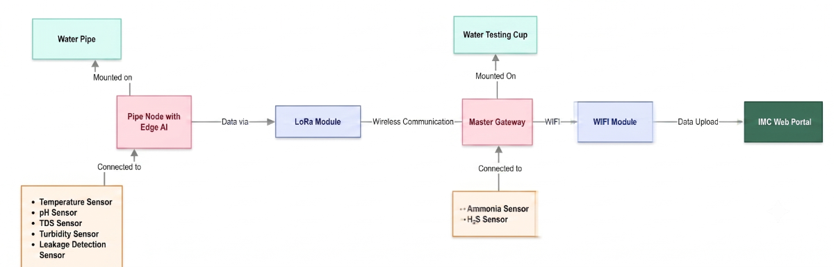
This architecture outlines a comprehensive end-to-end water monitoring system, transforming raw physical sensor data into actionable insights on a centralized web portal. The workflow is split between localized sensing at the pipe, a long-range communication network, a localized secondary testing station, and a cloud-based presentation layer.
- Localized In-Pipe Sensing: An Edge AI-enabled Pipe Node Battery/Solar-powered units is mounted directly on the water supply line, equipped with a sensor suite to continuously monitor vital water quality parameters (pH, TDS, Turbidity, Temperature) and infrastructure health (Leakage Detection). its install in every 10 Km and have a decentralized connectivity with Master gateway via LORA.
- Long-Range Wireless Network: Sensor data is transmitted wirelessly over a LoRa-based network, bridging the Pipe Node to a centralized, localized hub even over significant distances.
- Master Gateway Station: The wireless signals terminate at this gateway, mounted on a physical "Water Testing Cup," to test the water on ground / tank. serves as a localized hub to aggregate incoming data while conducting its own specialized sampling for critical contaminants like Ammonia and H2S.
- Cloud Connectivity & Visualization: The aggregated network data is pushed via a WiFi Module for secure upload to the internet, where it is presented on the "IMC Web Portal" for end-user monitoring and analysis.
3. Supplies & Components
Components For 1x Pipe Node Unit:
- 1 x Microcontroller: ESP32 (NodeMCU32 38 pin)
- 1 x Turbidity Sensor
- 1 x TDS Sensor
- 1 x Water PH sensor
- 1 x Water proof Temperature sensor (DS18B20)
- 1 x Microphone module : INMP441
- 3 x 20K ohm resistance 0.25 W
- 3 x 10K ohm resistance 0.25 W
- 1 x Communication: LoRa Ra-01 Module (SX1278)
- 1 x Li-Po Battery
- 1 x Li-po battery charging / V reg module
- 1 x 70x70mm Solar Panel
- 1 x 75mm dia PVC pipe
- 3 x 75mm Pipe End-Cap
- 1 x 75mm Pipe T
.jpeg)
.jpeg)
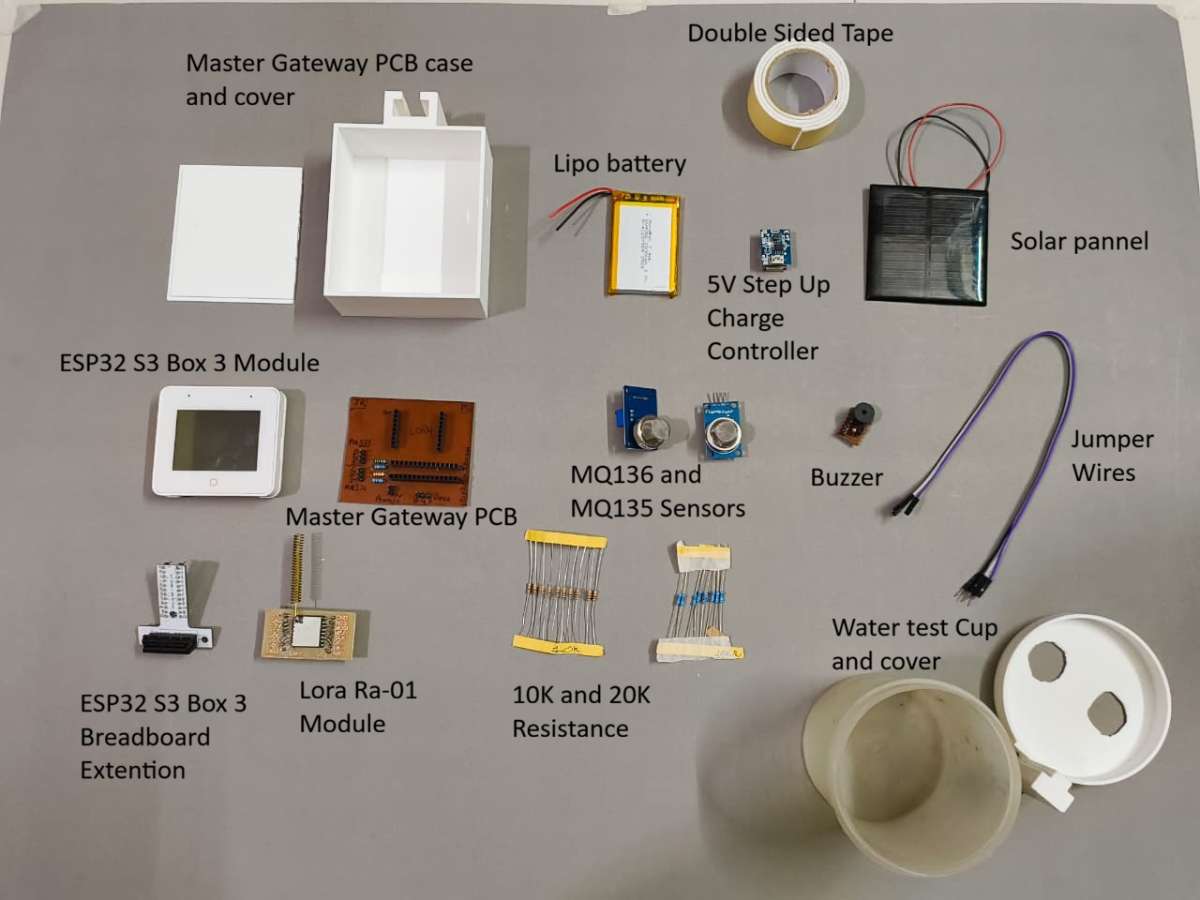
Components For 1x Master Gateway Unit:
- 1 x Microcontroller: ESP32 S3 Box 3(WiFi+ Touch-LCD)
- 1 x Communication: LoRa Ra-01 Module (SX1278)
- 1 x MQ-135 Ammonia (NH₃) Gas Sensor
- 1 x MQ-136 Hydrogen Sulfide Gas Sensor
- 2 x 20K ohm resistance 0.25 W
- 2 x 10K ohm resistance 0.25 W
- 1 x Buzzer
- 1 x Li-Po Battery
- 1 x Li-Po battery charging / V reg module
- 1 x 70x70mm Solar Panel
Tools
- 3D Printer (for enclosures and mounting parts)
- Soldering Kit (iron, solder wire, flux, wick and wire cutter)
- Screwdriver Kit (for M2/M3 hardware)
Software apps and online services
- Arduino IDE
- Edge Impulse
- Easy EDA
- Fusion 360
- Google Fire-Base
- Bambulab studio slicer
- Thonny Python
4. Building the Pipe Node
The Pipe Node is the frontline of the Jal Rakshak network. To function reliably in the harsh, subterranean environments of municipal distribution lines, the nodes requires a rugged, waterproof physical footprint combined with ultra-low-power, intelligent edge processing. This section details the complete engineering lifecycle of the node, from raw schematic to a deployed, Edge AI-powered device.
Part A: Hardware Fabrication & Assembly for Pipe Node
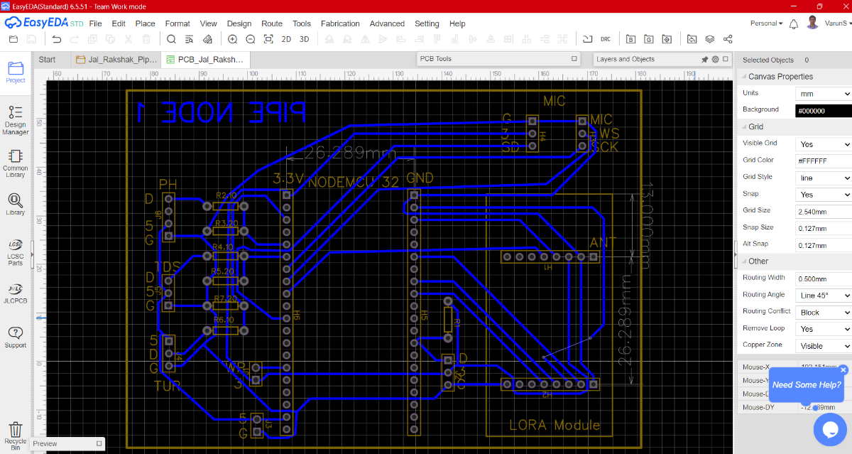
Step 1: PCB Design
A primary engineering challenge solved in this design was the logic-level mismatch between the sensors. The ESP32 microcontroller operates strictly at 3.3V, while the industrial water quality sensors (pH, TDS, and Turbidity) require a 5V working voltage. Connecting a 5V analog signal directly to an ESP32 analog pin would permanently damage the chip.
To safely interface these components without distorting data accuracy, I integrated individual voltage divider networks using precision 10k ohm and 20k ohm resistors. This safely steps down the 0–5V analog signal to a safe 0–3.33V scale matching the microcontroller’s ADC range:
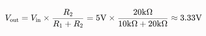
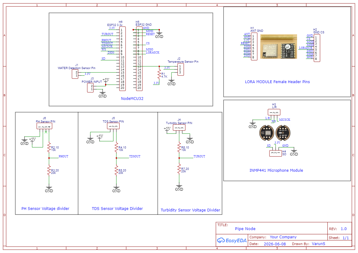
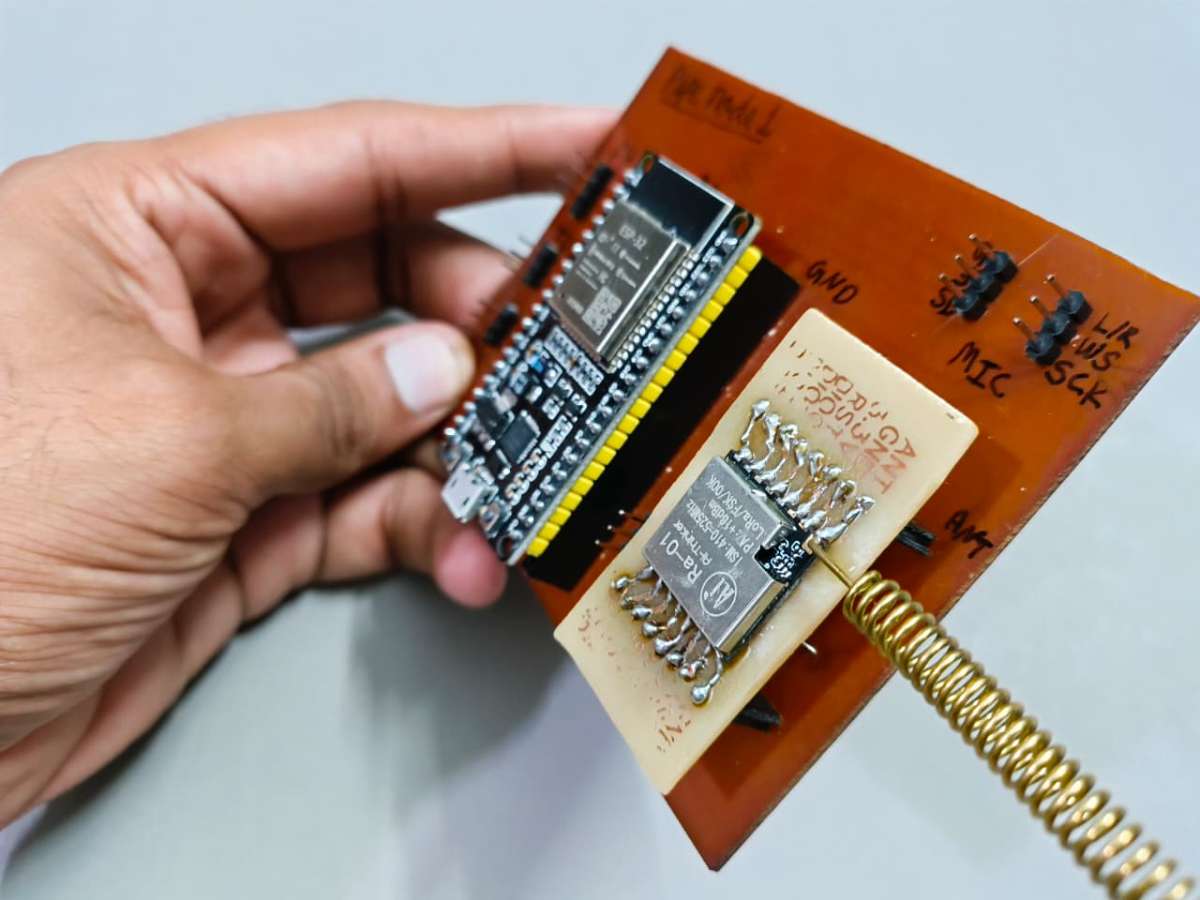
Meanwhile, the LoRa module, INMP441 Microphone, Digital Temperature sensor, and Water Presence Detection interrupt line run natively on the 3.3V power rail, ensuring optimized efficiency and minimal thermal signature inside the sealed housing. Below schematic diagram which is made in Easy EDA Std tool will show how the connections are made here in schematic i have used net label to connect pins.
Hardware Pin Configuration Matrix
To maintain clean signal routing and prevent cross-talk on the PCB layout, components were grouped by their communication architecture (SPI, I2S, Analog, and 1-Wire) and mapped to the microcontroller as follows:
| Component / Module | Function | ESP32 GPIO | Operating Voltage | Interface Type / Notes |
|---|---|---|---|---|
| LoRa Ra-01 Module | SCK | 18 | 3.3v | High-Speed SPI Clock |
| MISO | 19 | 3.3v | Master In Slave Out | |
| MOSI | 23 | 3.3v | Master Out Slave In | |
| CS/NSS | 21 | 3.3v | Chip Select (Active Low) | |
| RST | 22 | 3.3v | Hardware Reset Pin | |
| DIO0 | 25 | 3.3v | Packet Rx/Tx Interrupt | |
| INMP441 Mic Module | WS | 33 | 3.3v | Word Select (Left/Right Clock) |
| SCK | 32 | 3.3v | Continuous Serial Clock | |
| SD | 27 | 3.3v | Serial Data Out | |
| L/R | GND | GND | Grounded to GND pin | |
| Water Quality Sensors | pH Sensor | 34 | 5V to 3.3V | ADC1_CH6 via 10k ohm 20k ohm Divider |
| TDS Sensor | 35 | 5V to 3.3V | ADC1_CH7 via via 10k ohm 20k ohm Divider | |
| Turbidity | 36 | 5V to 3.3V | ADC1_CH0 via via 10k ohm 20k ohm Divider | |
| Water Sense | Temperature DS18B20 | 4 | 3.3V | 1-Wire Digital (Requires 4.7k ohm Pull-up) |
| Water Detection | 13 | 3.3V | Digital Interrupt |
For 5v power input from Voltage regulator i have added header pin to take power input.
Here is the designed PCB for Pipe node.
Files for PCB design in available in git hub repository : Link
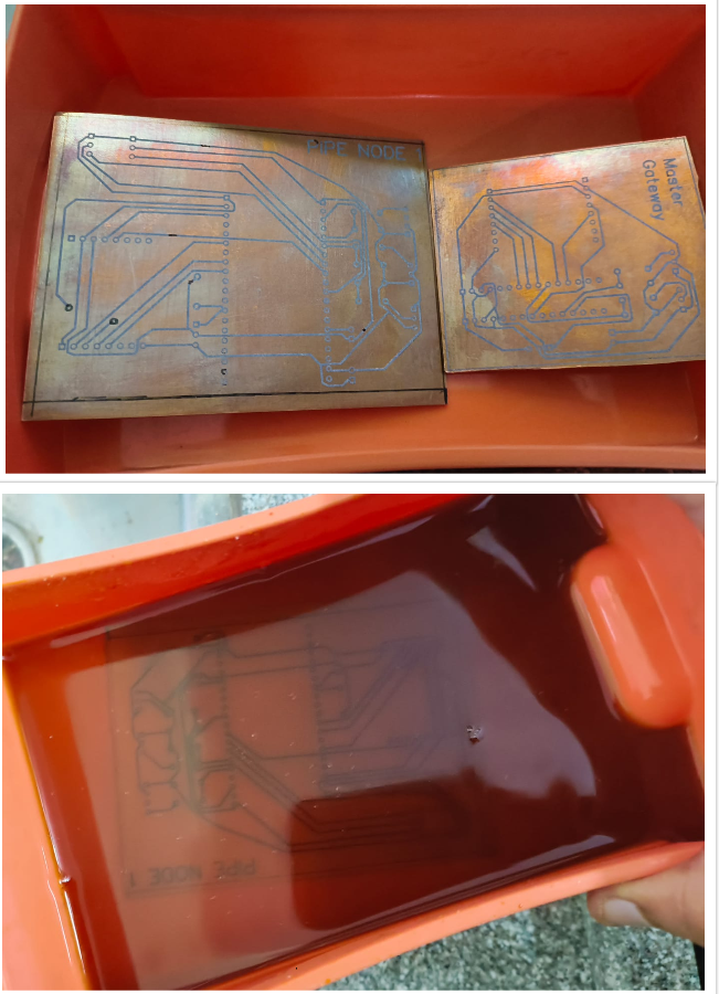
Step 2: PCB Fabrication & Assembly
To bring the schematic into the physical world, I chose a hands-on, custom fabrication approach. Rather than waiting weeks for industrial manufacturing, I fabricated the board in-house using the classic toner transfer and chemical etching method. This allowed for rapid prototyping and immediate physical verification of the layout.
The step-by-step fabrication and assembly workflow was executed as follows:
- Traces Export & Printing: Once the routing was finalized in Easy-EDA, I exported the bottom layer traces as a high-resolution PDF. I printed the mirrored artwork onto premium toner transfer paper using a laser printer set to maximum toner density.
- Thermal Transfer: The copper clad board was thoroughly scrubbed and degreased. I then aligned the printed transfer paper against the copper side and applied heat and uniform pressure using a hot iron. This fused the laser toner directly onto the copper, creating a precise, chemical-resistant mask for the traces.
- Chemical Etching (FeCl3): The prepared board was immersed in a custom-mixed bath of Ferric Chloride (FeCl3) and hot water. The hot water accelerated the chemical reaction, cleanly dissolving away the exposed, unprotected copper while leaving our circuit traces perfectly intact under the toner mask. After etching, the protective toner was stripped away with acetone.
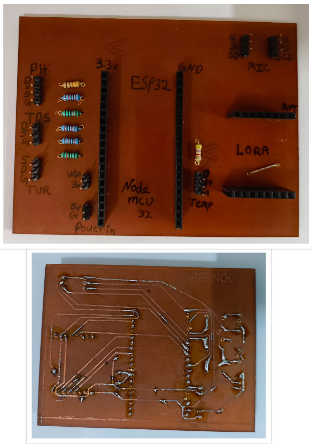
- Precision Drilling: Using a mini PCB drill press, I meticulously drilled out all the through-holes for the component pins and headers, ensuring perfect alignment with the etched copper pads.
- Component Assembly & Soldering: Instead of soldering the delicate ESP32 microcontroller, LoRa module, and sensor boards directly to the copper surface, I soldered high-quality male and female headers onto the board.
Design Rationale: The Advantage of Header Integration
Integrating pin headers instead of direct component soldering provides two critical engineering advantages for field deployment:
1. Modular Serviceability: If a sensitive sensor or communication module fails due to underground environmental stress or a power surge, it can be unplugged and replaced in seconds without desoldering or risking heat damage to the main PCB traces.
2. Optimized Airflow & Thermal Isolation: Elevating the modules off the surface of the main PCB creates a natural air gap. This significantly improves convective airflow within the sealed enclosure, preventing heat buildup from the power regulators and radio modules.
This soldering should be done while keeping track to the PCB design which allows us to get idea where to place which component.
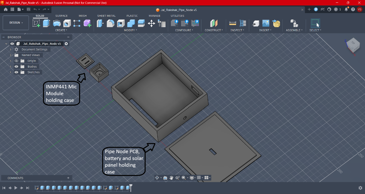
Step 3: CAD Design and 3D Printing
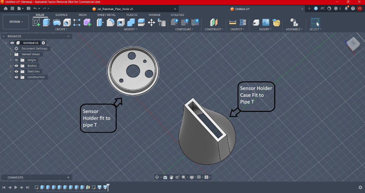
Operating in underground municipal environments means our electronics face a dual threat: mechanical impact and moisture ingress. To safeguard the system, I designed a split-enclosure architecture using Autodesk Fusion 360. Instead of forcing everything into a single bulky box, the system is separated into two specialized units: a centralized processing hub and a localized, waterproof sensor pod.
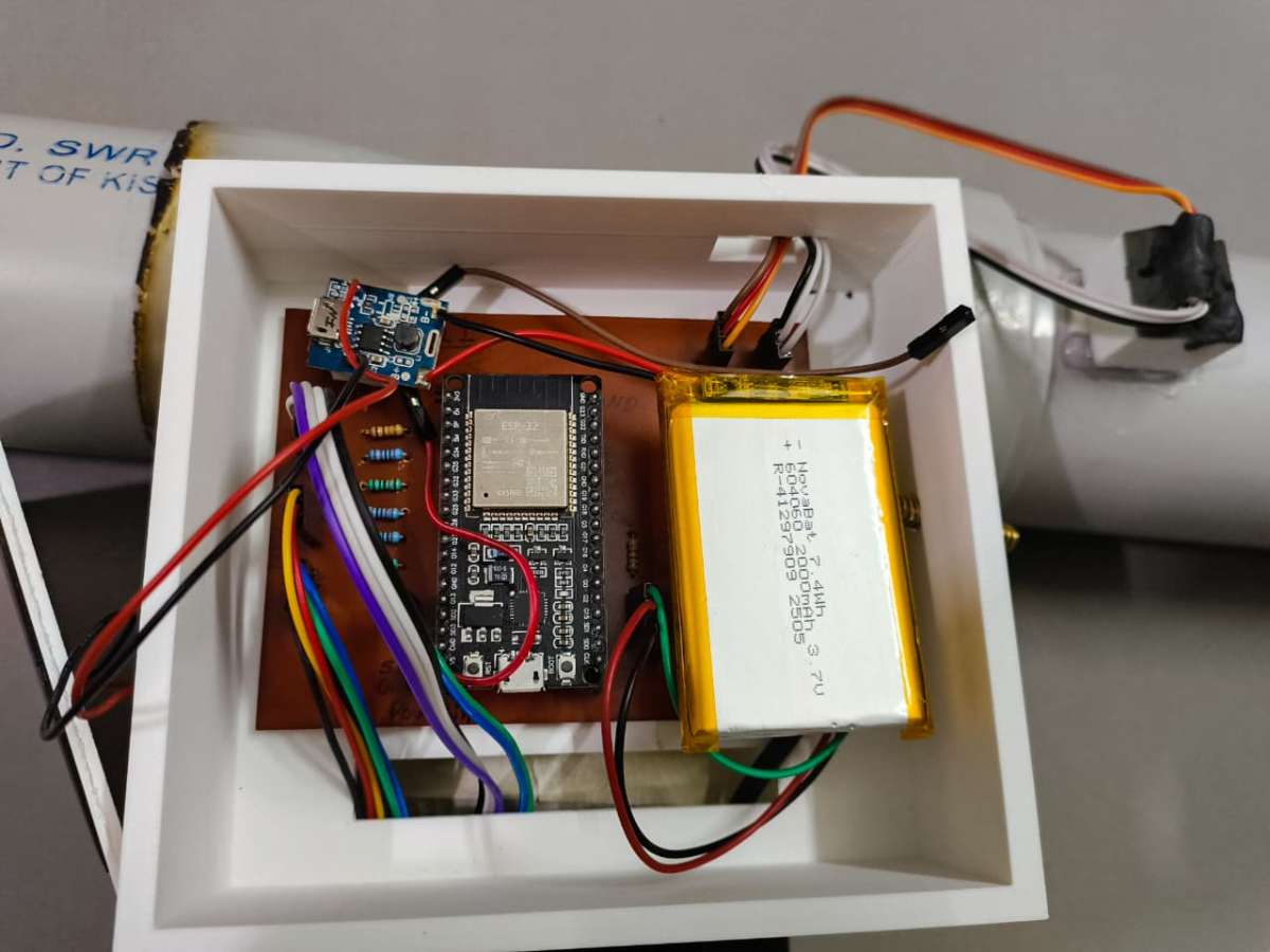
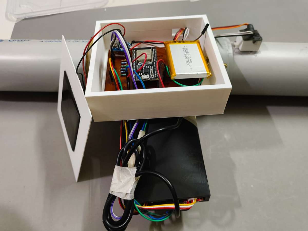
1. Enclosure Architecture 1: The Main Control Hub
This main housing acts as the command center, isolating the processing and power components from direct contact with fluid dynamics while maintaining a clean footprint for serviceability.
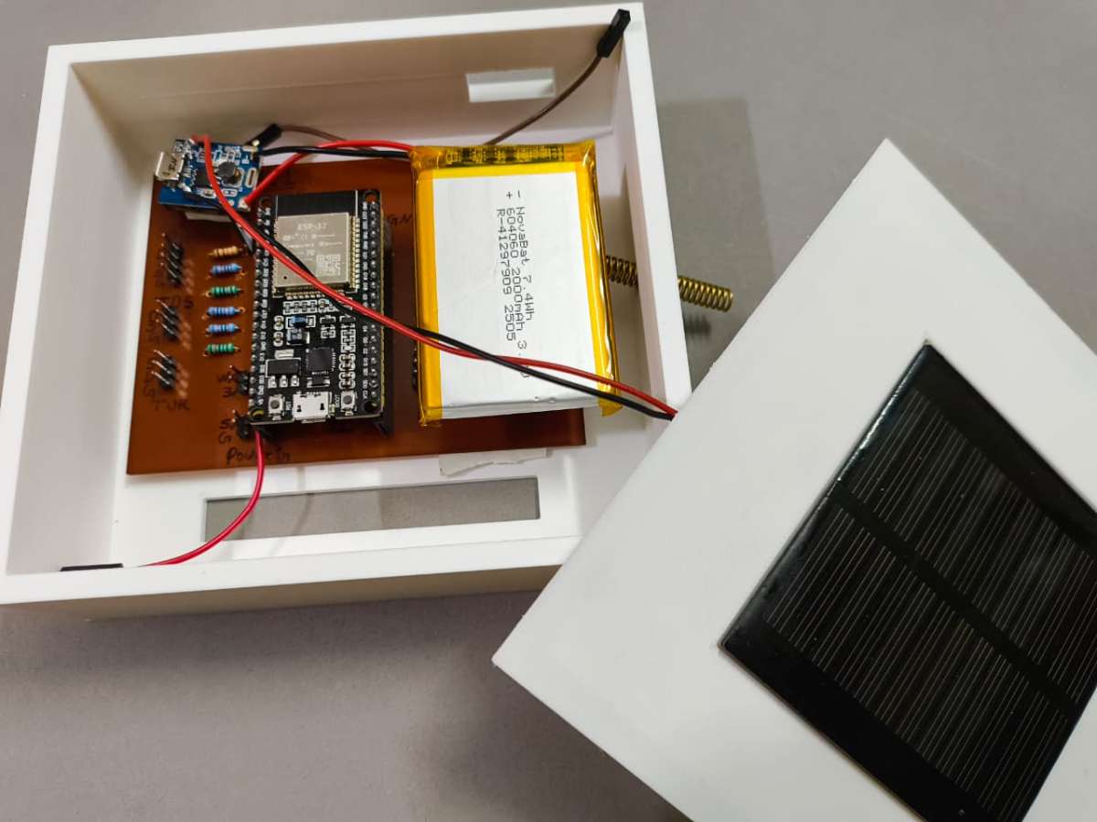
- All-in-One Power & Logic Bay: The interior layout is precision-molded to securely friction-fit the custom Pipe Node PCB, an lithium polymer battery, the TP4056 charging circuit, and the 5V/3.3V voltage regulation hardware with solar panel.
- Acoustic Edge AI Chamber: A dedicated, isolated mini-case is integrated into the top section of the enclosure specifically to house the INMP441 I2S microphone module. This positions the acoustic sensor flat against the structural apex of the pipe, allowing it to capture clear structural acoustics for leak and fracture detection.
- Environmental Cutouts: The housing includes dedicated, tight-clearance exit ports for the high-gain LoRa antenna and a M-sealed input pathway for the sensor wiring harness.
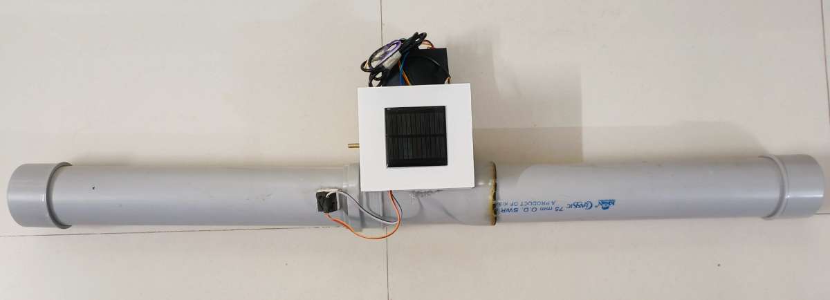
2. Enclosure Architecture 2: The T-Junction Sensor Pod
Because water quality sensors must interact directly with the fluid stream, protecting their exposed wiring and delicate breakout circuitry requires an entirely different engineering approach.
- T-Side Pipe Integration: This modular enclosure is engineered to clamp directly onto the "T-side" (T-junction flange) of standard municipal distribution lines, ensuring zero leaks and a flush structural mount.
- Hermetic Circuit Protection: The assembly utilizes a dual-piece system consisting of an internal sensor alignment holder and a heavy-duty, gasket-sealed case cover. This ensures that while the physical probes sit inside the water stream, their delicate terminal boards remain completely dry.
- 5-in-1 Sensor Array Placement: The holder features internal alignment channels engineered to simultaneously cradle five distinct probes:
- Temperature probe (1-Wire)
- pH electrode
- TDS copper pins
- Turbidity light-scattering probe
- Water Presence Sensor
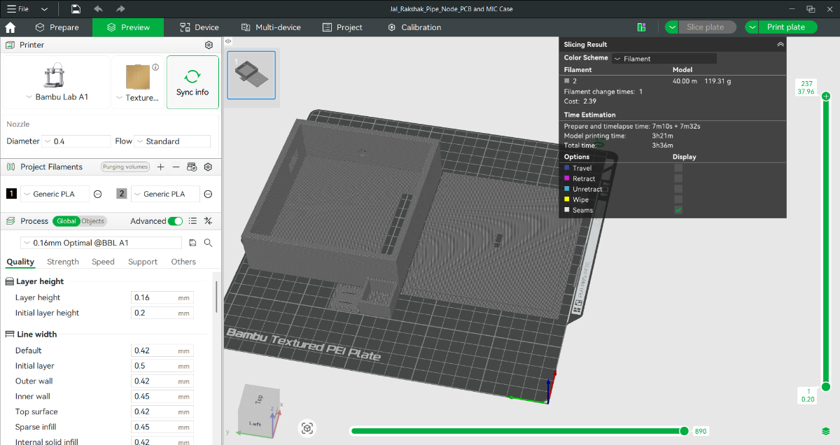
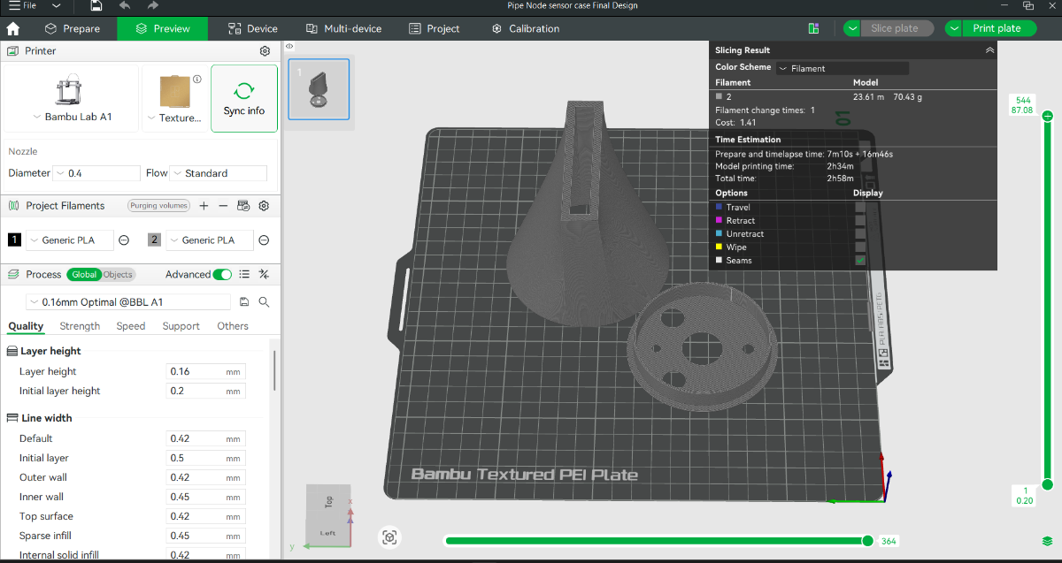
3. Fabrication & Slicing Profile
To turn these complex geometric models into rugged, field-deployable plastic parts, the slicing and manufacturing workflow was tightly controlled to maximize water resistance and interlayer bond strength.
- Production Hardware: Fabricated using a Bambu Lab A1 3D printer. The machine’s large build volume allowed multiple enclosure panels to be printed simultaneously, maintaining perfect dimensional tolerance across matching parts.
- Slicing Engine: All models were processed through Bambu Studio to configure optimized path planning, ensuring clean vertical walls around the critical sensor o-ring grooves.
- Material Selection (PLA+): Standard PLA was rejected due to its brittleness under mechanical stress. I utilized premium PLA+, which offers significantly higher impact resistance and superior interlayer adhesion—a necessity for enduring subterranean pressure variants.
- Print Settings Profile:
- Nozzle Diameter: 0.4mm (Balances precise internal snapping clips with robust outer walls)
- Layer Height: 0.16mm (High-quality fine resolution to minimize stair-stepping on threaded sections and ensure watertight seals)
- Infill Density: 25% Gyroid (Provides uniform multi-directional structural strength against ground compression)
- Wall Loops: 3 Layers (Thick outer shell to prevent micro-porosity water leaking through layers)
Files for 3D cad file are available in git hub repository : Link
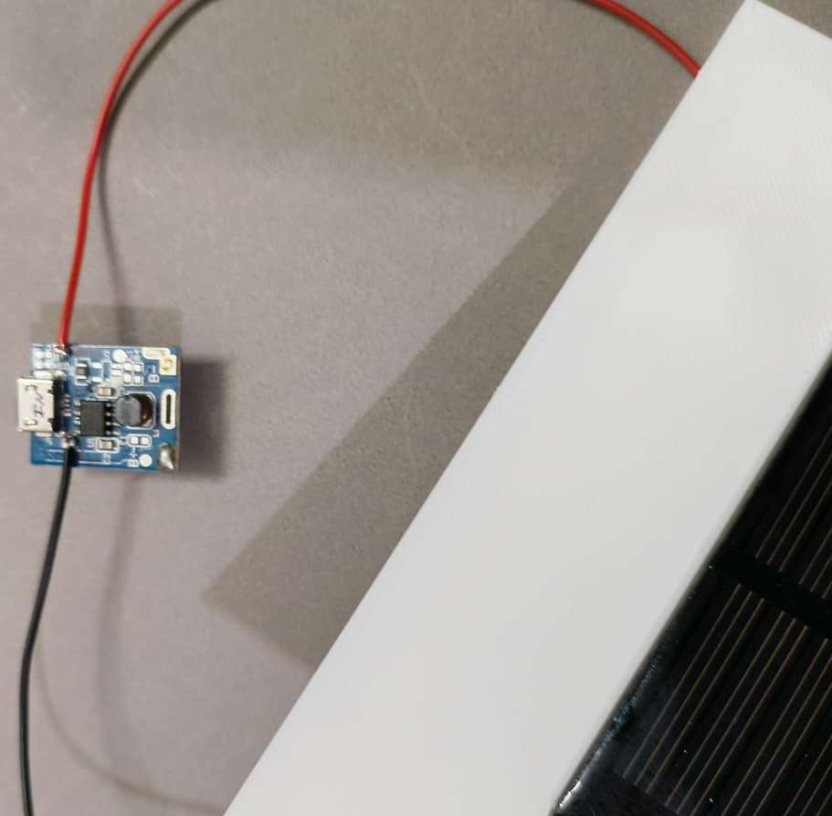
Step 4: Solar Wiring and Power setup
To ensure total energy independence from the main power grid, the Pipe Node utilizes a self-sustaining solar harvesting subsystem. The core of this power architecture is an All-in-One 5V Step-Up Charge Controller Module. This module acts as the energy traffic controller, it safely manages variable solar voltage to charge a high-capacity Lithium-Polymer (LiPo) battery while simultaneously boosting the battery's nominal 3.7V output to a rock-solid 5V rail required by the water quality sensors.
The electrical wiring and assembly sequence were performed in the following precise order :
- Step 1: Solar Panel Input Integration The positive and negative leads from the outdoor-rated solar panel were routed into the housing and soldered directly to the Solar Input pads (VIN+ / VIN-) on the charge controller module. This establishes the primary power harvesting pathway.
.jpeg)
.jpeg)
- Step 2: 5V Regulated Output Routing To supply power to the sensor array and the main circuit, heavy-gauge jumper wires were soldered to the 5V Boost Output pads (VOUT+ / GND) of the module. These wires run directly to the power distribution rails on our main Pipe Node PCB.
.jpeg)
- Step 3: LiPo Energy Storage Connection The final connection involved soldering the positive (Red) and negative (Black) leads of the 3.7V LiPo battery to the dedicated Battery Terminals (B+ / B-) on the controller. Keeping this step for last prevents the boost circuitry from running in an unstable, unbuffered state while handling loose wires.
.jpeg)
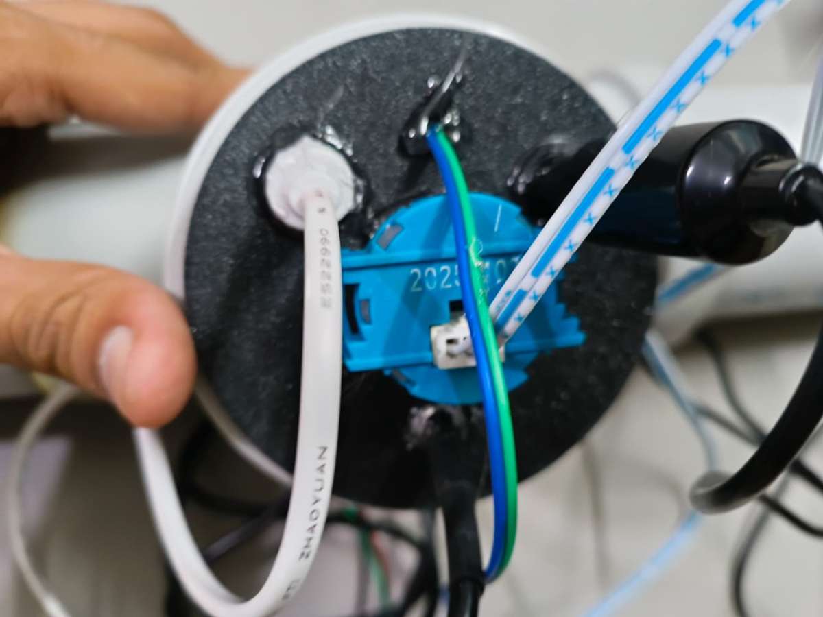
Step 5: Housing Assembly
Bringing the individual hardware, power, and enclosure elements together into a single, cohesive, field-ready unit requires a meticulous mechanical assembly workflow. Because this node will operate in high-humidity subterranean valve chambers, waterproofing and cable management are strictly prioritized at every step to prevent moisture-induced short circuits.
The structural assembly process is executed in four distinct phases:
Phase 1: Main Control Hub Internal Assembly
This phase focuses on securing the core electronic brains and power distribution modules inside the primary 3D-printed case.
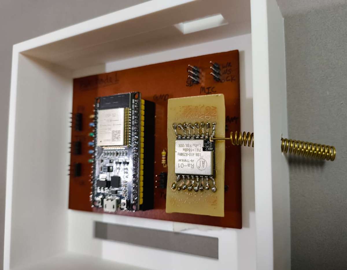
- Step 1: Board Population Insert the NodeMCU-32S (ESP32) development board and the LoRa communication module firmly into their designated male/female pin headers on the custom PCB. Double-check alignment to ensure no pins are offset.
- Step 2: Base PCB Mounting & Antenna Routing Apply heavy-duty, high-bond double-sided tape to the bottom of the main PCB. Carefully lower it into the main Pipe Node case. While lowering, route the flexible or rigid LoRa antenna through the dedicated chassis hole so it extends fully outside the case for unobstructed signal propagation. Press the PCB down firmly to lock it into place.
- Step 3: Power Subsystem Securing Using the same high-bond double-sided tape, mount the 5V Step-Up Charger module and the high-capacity LiPo battery onto unpopulated, insulated sections of the PCB base. Ensure the battery wires are clear of any sharp component pins to avoid punctures.
Phase 2: Acoustic Edge AI Pod Assembly
This section details the assembly of the isolated microphone capsule that tracks acoustic vibration fingerprints directly from the pipe walls.
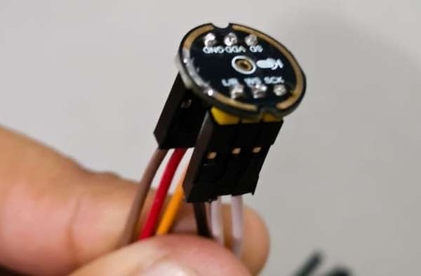
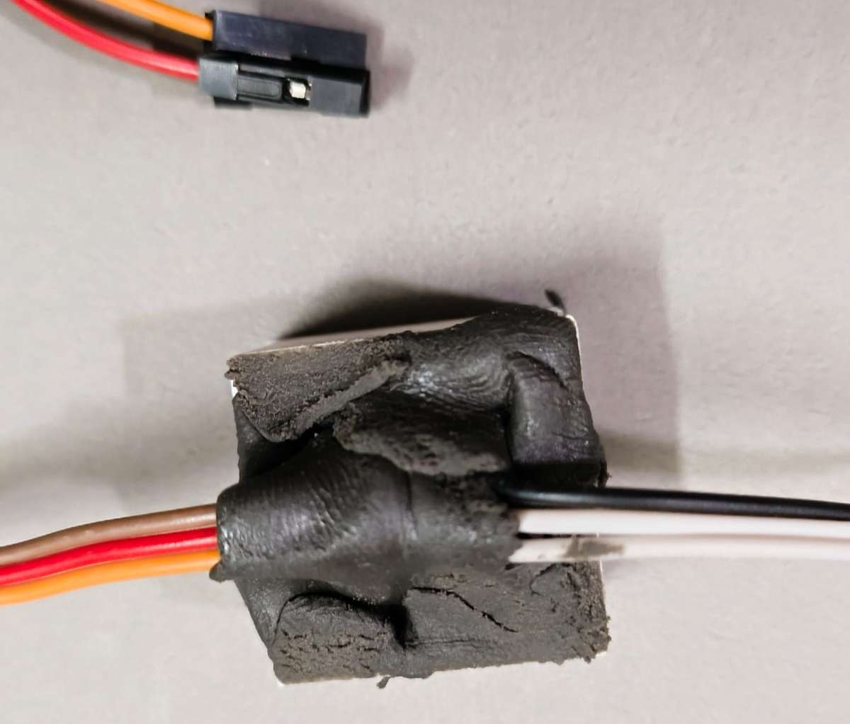
Step 4: Microphone Potting & Wire Mapping Solder color-coded jumper wires to the INMP441 I2S microphone module.
Crucial Engineering Note: Create a written log of your jumper wire color-to-pin mapping (e.g., Red for VCC, Black for GND, Yellow for WS, White for SCK, Green for SD) before sealing the module.
- Place the microphone inside its custom mini-casing and secure its position with a hot glue gun. Once fixed, pack the rear of the enclosure tightly with M-Seal wet-set epoxy putty to create a dense, waterproof barrier that locks out moisture and forces acoustic vibrations to pass cleanly through the sensor face.
.jpeg)
Phase 3: T-Junction Sensor Pod Integration
This phase couples the water quality probes with the structural plumbing elements using a rugged, multi-sensor alignment array.
- Step 5: T-Pipe Assembly & Probe Mounting
- Fit your structural PVC pipes securely into both straight ends of the plumbing T-junction.
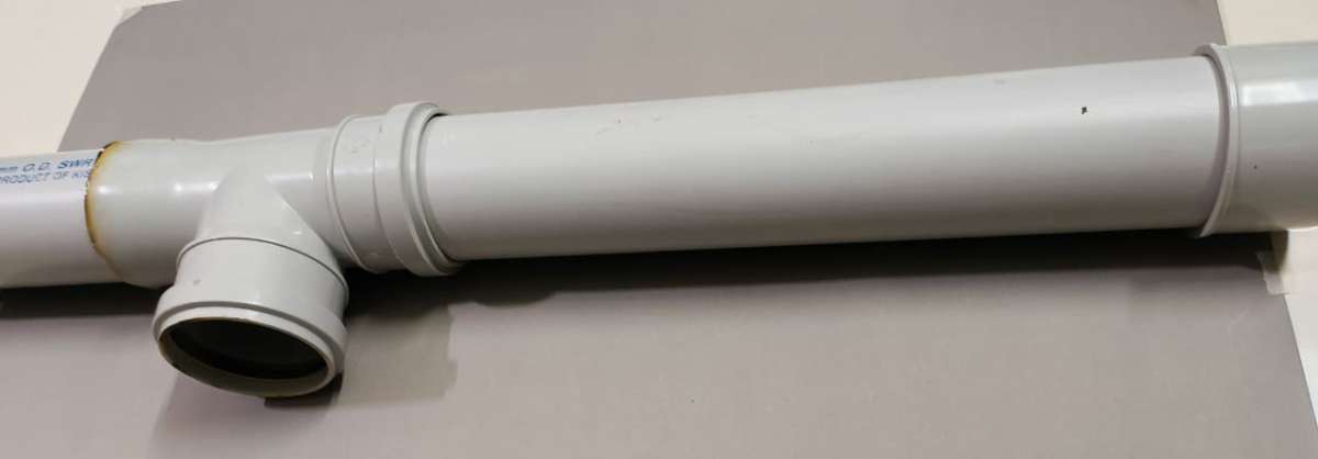
- Apply a generous layer of high-strength adhesive (like Fevi-bond or PVC solvent cement) to attach the custom 3D-printed sensor holder to the third (orthogonal) opening of the T-junction.
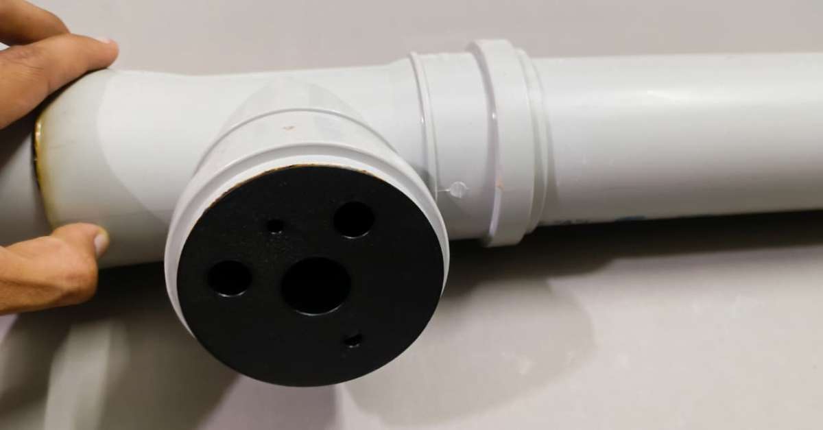
- Insert the five core probes (Temperature, pH, TDS, Turbidity, and Water Presence) into their form-fitting alignment channels.
- Pack the external mounting side heavily with M-Seal wet-set epoxy putty to create a permanent, pressure-resistant seal around the probe bodies.
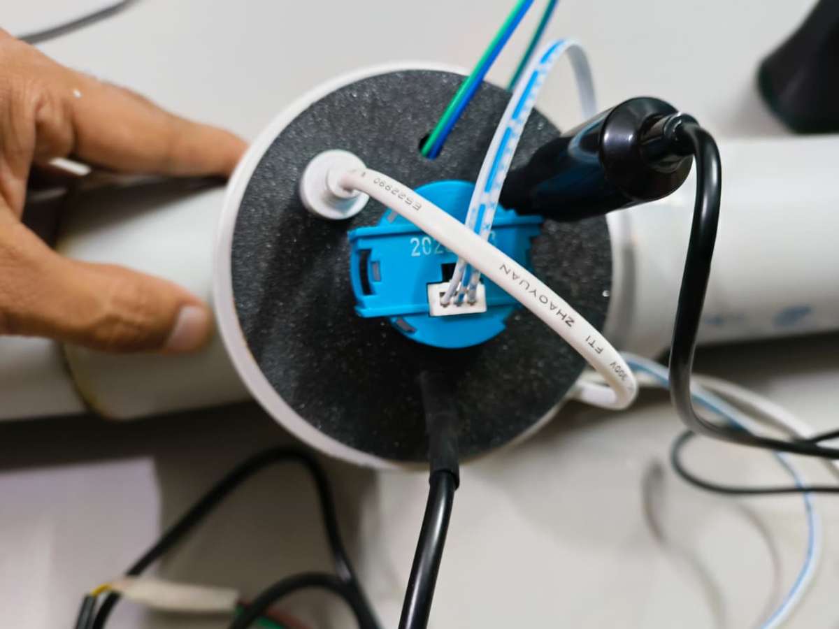
- Step 6: Converter Board Layout Connect the raw analog leads from the pH, TDS, and Turbidity probes to their respective signal conditioner/converter breakout boards.
- Line the interior base of the separate 3D-printed sensor case with high-bond double-sided tape and press the converter boards down into an organized grid layout.
- Step 7: Harness Extraction & Pod Sealing Carefully group all wiring harnesses, ensuring every single lead is explicitly labeled or color-identified by sensor type before it is covered.
- Route the entire bundled wiring harness cleanly out of the sensor housing. Mount the sensor case directly over the pipe T-junction mechanism, shielding the fragile electronics, and seal all exterior seams completely with M-Seal wet-set putty.
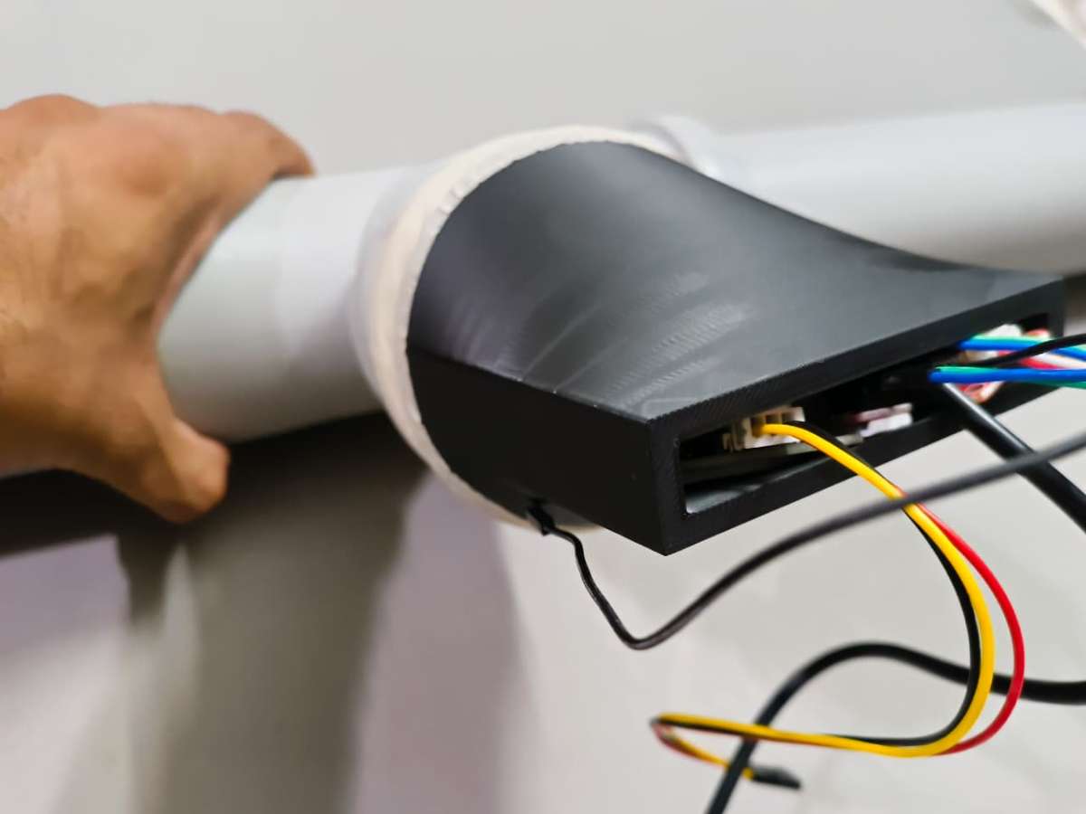
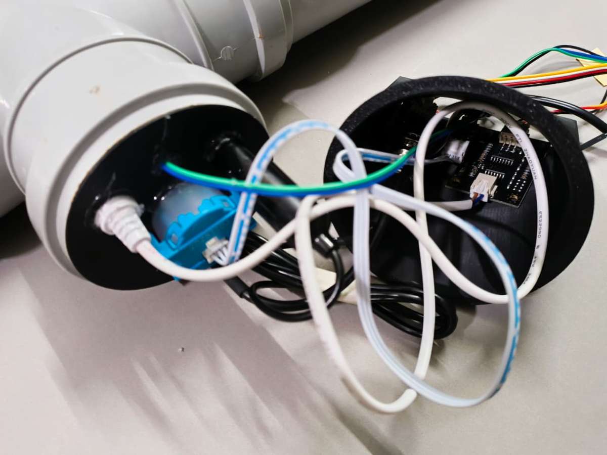
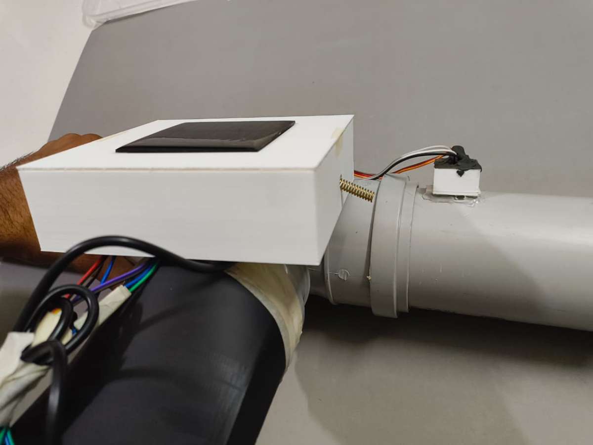
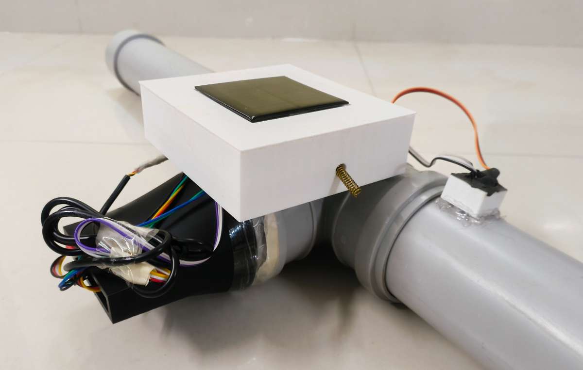
Phase 4: System Integration & Cable Management
The final phase bridges the sensor pod to the main control hub, completing the localized hardware loop.
- Step 8: Header Patching & Strain Relief Route the bundled wiring harness coming out of the T-junction sensor pod directly into the cable input port of the main Pipe Node case. Carefully plug each individual wire into its corresponding male/female header pin on the PCB, using your pin configuration chart. Organize any excess wire length cleanly within the open spaces of the enclosure using small zip-ties to prevent any internal wire strain or catching.
- Step 9: Final Enclosure Sealing & Mechanical Mounting Place the matching top cover onto the main Pipe Node chassis. Apply a continuous bead of M-Seal or silicone sealant along the perimeter seam to lock out the environment. To finalize the build, apply a heavy coat of structural adhesive to mount both the sealed main controller housing and the acoustic microphone pod firmly onto the structural frame of the PVC pipe array.
Part B: Code & Edge AI Deployment for Pipe Node
Hardware is only as smart as the code driving it. To prevent the next water infrastructure crisis, the Pipe Node doesn’t just dump raw data into the airwaves. Instead, it processes acoustic and environmental information directly at the edge.
This section details how the machine learning model was trained using Edge Impulse, how the local development environment was configured, and the foundational firmware logic that enables the node to run autonomously underground for years on battery power.
Step 1: Pre-Requisite for Node Code (Edge AI Setup)
Before uploading the final Node firmware, we must prepare the machine learning (ML) model that runs locally on the ESP32 pipe node. This is accomplished using Edge Impulse Studio, a development platform for engineering and deploying edge AI models directly to resource-constrained embedded systems.
By deploying this pipeline, we bring intelligence directly onto the pipeline network. The inference runs entirely on the Node itself without relying on internet access, cloud latency, or cellular handshakes.
Acoustic Classification for Subterranean Leak Detection
For the Jal Rakshak project, we focus on high-frequency audio classification using the onboard INMP441 I2S MEMS Microphone Module:
- Data Collection: Record real acoustic signatures of internal pipe dynamics (leaks, cracks, standard pressurized flow) and ambient urban noise boundaries (traffic, roads, soil vibrations).
- Feature Extraction: Raw time-series audio is converted into digital spectrograms (MFCCs), turning acoustic waveforms into visual maps of frequency and amplitude over time. This uncovers the hidden acoustic signatures of moving water versus background noise.
- Model Training: A 1D Convolutional Neural Network (CNN) is trained to classify data into two discrete target labels:
leakageandnoise. - Deployment: The optimized model is compiled into an Arduino library. The ESP32 executes inference locally inside the pipe node casing, processing audio data in real time without blocking routine sensor polling or LoRa communications.
Why This Matters: > This architecture converts every Pipe Node into an intelligent digital sentinel. Instead of manually sweeping lines or checking gauges, the nodes constantly listen to the infrastructure. They make real-time edge decisions without cloud dependency and broadcast immediate emergency alerts through the LoRa link the second a line fractures.
Building the Project Environment
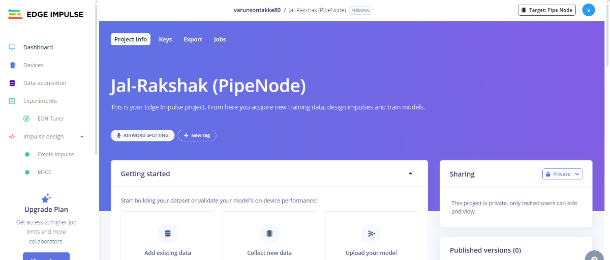
1. Create the Edge Impulse Project
- Open Edge Impulse Studio.
- Log in with your credentials and select Create New Project.
- Name the project descriptively:
Jal-Rakshak (PipeNode).
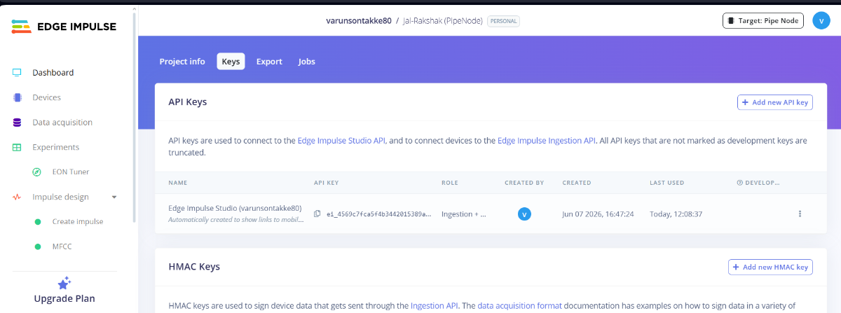
2. Retrieve the Project API Key
- Navigate to your project dashboard and click on the Keys tab.
- Locate the Project API Key and copy it to your clipboard. This token bridges your local hardware data-logging tools directly with the cloud platform.
The Data Collection Challenge & Solution
One of the steepest hurdles in tinyML development is streaming raw audio or image frames from an embedded system to an ML platform for training. While numeric streams (like TDS or temperature numbers) scale easily over raw text terminals, high-frequency raw audio buffers over standard serial interfaces often bottleneck, forcing developers to log data onto SD cards, manually swap cards, and extract files.
The Flask Data Uploader
To bypass this friction and rapidly iterate our model, I modified a desktop Flask-based data capture application referred from forest Guard project by Mukesh Shankhala from maker brains that creates a seamless bridge between the ESP32 and Edge Impulse Studio:
- ESP32 Data Streamer: A lightweight, dedicated Arduino sketch is flashed onto the ESP32 node. Its sole job is to initialize the I2S bus, pull raw audio samples from the INMP441 DMA buffer, and blast them line-by-line across the Serial USB port.
- Flask Desktop Application: Running locally on a PC, this Python tool listens to the designated COM port, captures the incoming binary audio chunks, writes them into clean
.wavaudio files, and uses your copied Edge Impulse API Key to automatically upload and sort the files into your cloud dashboard.
Core Benefits:
- Eliminates the need for external SD card hardware or manual file transfers.
- Automatically organizes, structures, and labels audio samples on the fly.
- Significantly speeds up training times by allowing new samples to be captured and verified in seconds.
Modified Data Collector Edge Impulse Data Tool is available in git hub repository : Link
Executing the Data Collection Workflow
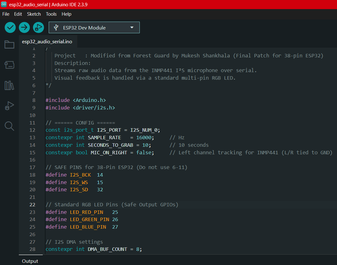
1. Loading the ESP32 Audio Serial Code
Before using the Flask uploader, the node must be programmed to stream audio parameters over the USB port:
- Open the Arduino IDE and go to File then Preferences.
- Add the Espressif Board URL link to your board manager. Navigate to Tools then Board then Boards Manager, search for
esp32by Espressif Systems, and install the latest stable package. Open your custom
esp32_audio_serial.inosketch. This routine initializes the I2S microphone bus and sets up a configurable timing parameter:constexpr int SECONDS_TO_GRAB = 10;(Defaulted to 10-second capture windows).- Select your target board, enable USB CDC On Boot, select the active COM port, and upload the code to your node.
2. Running the Desktop Flask Tool
- Download or open your local project repository folder containing the Edge Impulse Data Tool.
Open your command prompt or terminal inside the
Edge Impulse Data Tool/directory and spin up the Python server:Bash
python app.py
Open your web browser and navigate to the local hosting page: http://127.0.0.1:5000/ to launch the custom Data Collection Dashboard.
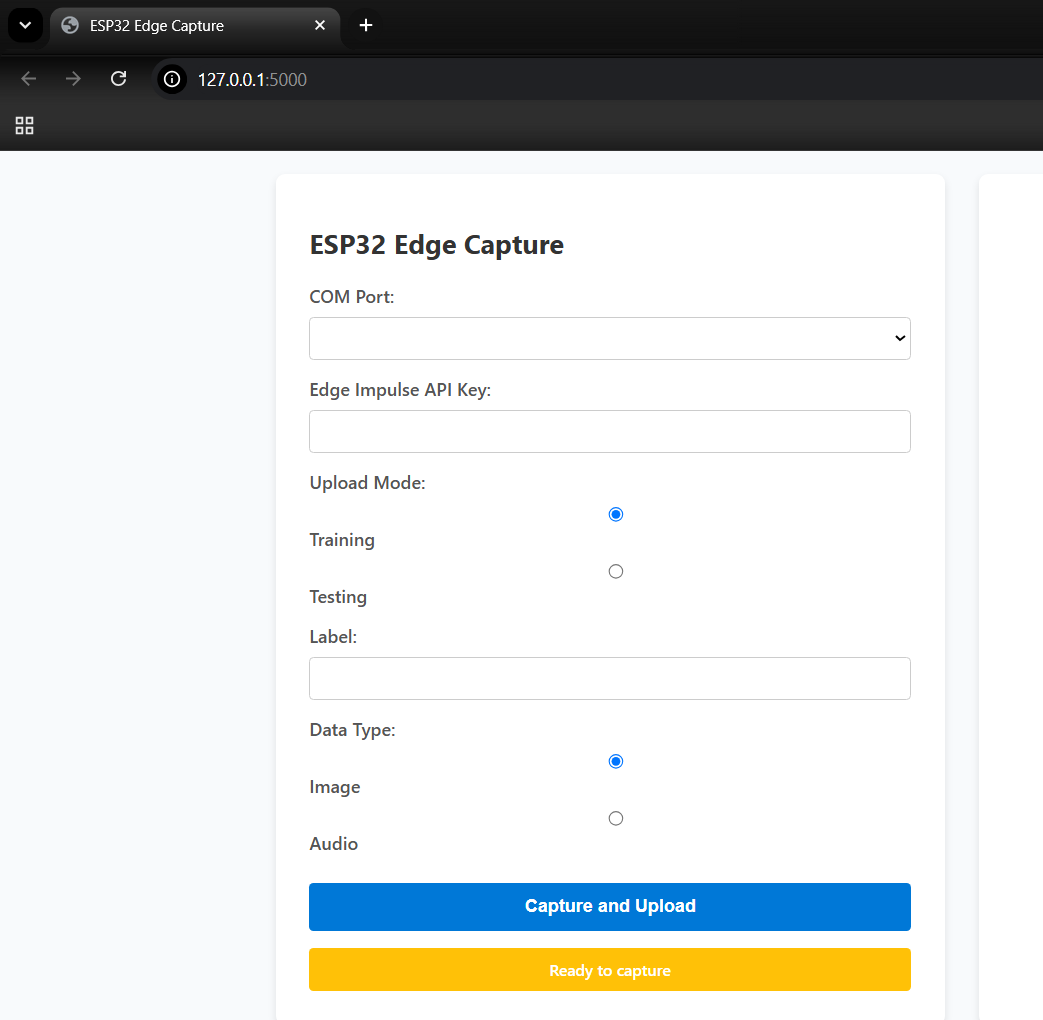
3. Capturing Labeled Audio Samples
- Select COM Port: Choose the active serial port connected to your streaming ESP32 node.
- Paste API Key: Input the unique token copied from your Edge Impulse Dashboard.
- Choose Mode: Set the sample target category to Training (or Testing for validation sets).
- Enter Label: Input the appropriate classification category:
leakageornoise. - Click Capture: The Flask application will begin recording. The node's onboard indicator LED will glow solid green during the active 10-second audio capture. Once the LED turns off, the tool wraps the audio chunk into a
.wavfile and pushes it directly into your Edge Impulse Studio environment.
Do watch this video which describes the data collection.
- Data Collection video link
- Data Set Folder available in Github repository : Link
Building & Processing the Dataset
A robust, varied dataset is the single most important factor for achieving a reliable edge AI model.
- Gathering the
noiseClass: Mount the microphone chassis array exposed near active environments to capture routine ambient city noise (traffic dynamics, wind, structural vibrations, passing vehicles, human chatter). Capture at least 120 seconds of data across these variations to prevent false-positive leak alarms. - Gathering the
leakageClass: Clamp the sensor directly onto your pipeline prototype testing rig. Capture audio runs of distinct internal water flow velocities, structural high-pressure hiss, and micro-fracture leak vibrations. Accumulate 120 seconds of raw leak data across varying distances from the leak source to help the network generalize well.
.png)
Splitting Samples into 1-Second Features
Because our raw files are uploaded in 10-second fragments, we must fragment them into tighter slices to optimize the embedded model's memory profile and processing speed:
- In Edge Impulse Studio, open the Data Acquisition dashboard.
- Select an uploaded 10-second file, click the options menu icon (three dots), and select Split Sample.
- The automated tool will slice the audio track into ten separate 1-second chunks. For your
leakagefiles, ensure the split boundaries capture the distinct audio signatures cleanly. Click Split to save.
.png)
Designing & Training the Neural Network Impulse
With your dataset split into 1-second segments, navigate to the Create Impulse tab to configure the structural processing pipeline:
- Window Profile: Maintain the Window Size at 1000ms (1 second) to match our split files.
- Processing Block (MFCC): Add the Audio (MFCC) processing block. Mel-Frequency Cepstral Coefficients convert raw sound waves into compact visual spectrograms, turning acoustic patterns into recognizable geometric features for the classifier.
- Learning Block (Classification): Add a Classification block to map the network outputs to our target labels (
leakageandnoise). Click Save Impulse.
.png)
Feature Generation
- Navigate to the MFCC item under the Impulse Design sub-menu.
- Keep the optimized default parameters and click Save Parameters, then click Generate Features.
- Once processing concludes, review the Feature Explorer point cloud graph. Each plotted element represents a 1-second clip. Successful training is indicated by clear, distinct spatial cluster separation between the
leakagedata points and the baseline urbannoisepoints.
.png)
Neural Network Training
- Navigate to the Classifier tab on the left-side panel.
- Configure the neural network parameters with the following optimized edge defaults:
- Training Cycles (Epochs): 100
- Learning Rate: 0.005
- Network Architecture: 1D Convolutional Neural Network (CNN) — ideal for audio feature arrays.
- Click Start Training.
.png)
Analyzing the Model Performance Results
Upon training completion, the platform generates validation and on-device deployment projections to confirm model stability before compilation:
- Validation Accuracy: ~99.5% (indicating excellent classification accuracy across the validation datasets).
- Confusion Matrix:
leakageaccurately classified 99.5% of occurrences.noiseaccurately classified 99.4% of occurrences (confirming zero false alarms from city traffic noise).
- Performance Metrics: Precision: 0.99 | Recall: 0.99 | F1-Score: 0.99
On-Device Compute Optimization Diagnostics:
The compilation engine calculates the hardware resource footprint on an embedded CPU architecture to verify memory safety:
- Inference Latency: ~4 milliseconds (ultra-fast processing loops).
- RAM Consumption: ~12.6K (well within the ESP32’s available SRAM footprint).
- Flash Footprint: ~45.6K (leaves ample space for our LoRa stacks and hydration sensor logic).
Exporting the Deployment Library
Once performance figures are verified, the model must be packed into a portable deployment format:
- Navigate to the Deployment menu tab in Edge Impulse Studio.
- Under the deployment target configurations selection matrix, click Arduino Library.
- Scroll to the base of the page and click Build.
- The platform will automatically download a standalone, compressed deployment library file to your local machine, titled something like:
ei-jal-rakshak-(pipenode)-arduino-1.0.3-impulse.zip. This archive is now ready to be imported directly into the Arduino IDE to act as the autonomous brain of your Pipe Node.
.png)