
Introduction & The Smart Grid Challenge
Traditional solar charge controllers are static and reactive. They charge batteries without considering future weather, are blind to battery health/aging, and operate as completely isolated units. When a localized grid faces a demand spike or a cloud shadow, it has no way to balance the load, leading to energy waste or battery damage.
The LIFE (Local Intelligence for Energy) Node project changes this. It transforms a basic solar charger into a self-aware, intelligent participant in a decentralized smart grid. Using a custom ESP32-C3 carrier board, on-device quantized machine learning models, and peer-to-peer communication, each node autonomously predicts solar generation, scores its own uncertainty, and shares surplus energy with neighboring nodes over a WiFi mesh network.
System Design & Architecture
The system operates entirely on the edge, without relying on a central server. This eliminates any single point of failure.
Every node runs an independent decision pipeline:
- Sensor Ingestion: Telemetry is captured locally from a Light Dependent Resistor (LDR), DHT11, and current/voltage sensors.
- LSTM Solar Prediction: A lightweight, quantized LSTM model predicts solar availability for the next step.
- Uncertainty Scoring: A safety gate calculates the confidence score of the prediction.
- RL Control Policy: If confidence is high, an on-device Reinforcement Learning (RL) model chooses the optimal charge rate and energy route (
BATTERY,LOAD,GRID, orDUMP). - Fallback Safety: If uncertainty is high, a deterministic fallback rule replaces the AI to guarantee system safety.
NOTE
Safety Crossover Gate: If the weather transitions suddenly (e.g., a storm hits) and the ML model's uncertainty exceeds 0.75, the node immediately bypasses AI control and falls back to hardcoded safety rules to protect the lithium battery.
Decentralized Edge AI: How the LIFE Microgrid Operates in the Real World
Here is a detailed look at how the artificial intelligence operates across the network of energy nodes under real-world scenarios.
1. Dynamic Weather Adaptation
- The Rainy Day (Aggressive Prep Mode): When weather monitoring APIs and local sensors detect rising humidity and incoming rainfall, the AI predicts that solar generation will soon crash. To protect the household, it goes into Aggressive Mode, pulling maximum charge into the batteries to hit 100% capacity before the sun vanishes.
- The Sunny Day (Health-First Charging): When the AI forecasts a 0% cloud cover sunny day, it knows it has hours of guaranteed sunshine. Instead of fast-charging the battery—which generates high heat and degrades the cells thus the AI chooses battery health over speed. It drops the charge rate to a gentle speed, keeping the battery cool and extending its overall lifetime while still reaching full charge by sunset.
2. Learning User Consumption Patterns
- Smart Energy Buffering: The AI tracks daily usage habits. If it learns the home regularly runs high-power appliances at 6:00 PM, it coordinates the system to hold battery reserves intact leading up to that hour, using tail-end afternoon solar for immediate needs. This ensures your home runs on free solar during peak grid pricing hours.
3. Predictive Maintenance (Soiling & Dust Detection)
- The Dust Alert: It is a bright afternoon with equivalent sunlight and temperature to a day logged last year. However, the AI notices the solar panel output is 22% lower. By checking the battery's internal resistance and finding no defects, the AI deduces the panel is dirty. It notifies the user: "Solar panel output degraded by 22% due to dust/soiling. Please clean panels to restore efficiency."
4. Smart Node Coordination (P2P Sharing & Grid Export)
- Decentralized P2P Sharing: If your node has a fully charged battery and excess solar power, while a neighbor's node broadcasts an energy deficit due to heavy appliance use, the AI coordinates. It calculates the distances to neighboring nodes to find the most optimum electrical path (minimizing transmission line losses) and redirects the surplus power directly to the neighbor's home.
- Automatic Grid Arbitrage: If batteries are full across your local network and generation remains high, the AI dynamically decides to export the excess energy back to the utility grid, selling power at peak payout rates to generate revenue automatically.
Hardware Assembly
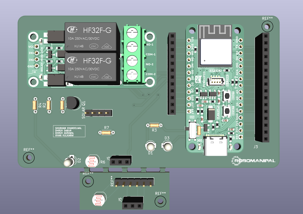
The hardware is built around a custom 2-layer PCB designed in KiCad. You can build it step-by-step:
Step 1: Brain & Communication
We used the ESP32-C3-MINI-1-N4 module for low-power processing, built-in WiFi mesh capabilities, and enough processing power to handle on-device machine learning inference.
Step 2: The Charger Modification
The charging path uses a CN3065 solar charger IC. To make this charger "software-defined," we added a BJT transistor switch to the ISET pin. By toggling this transistor, the ESP32 can switch an additional resistor in parallel, allowing the code to programmatically select between Slow/Trickle Charge and Fast Charge rates based on AI decisions.
Step 3: Smart Switching Relays
We integrated two heavy-duty relays:
- Relay 1 (Load): Connects or disconnects the local household load (supporting emergency load shedding).
- Relay 2 (Grid): Directs surplus energy onto the shared microgrid line to export power.
Step 4: The Snappable Sensor Array
A key part is the Mousebite Snappable Array. The LDR and DHT11 sensors are printed on a perforated tab. You can snap this array off the main board and run flex cable to mount the sensors directly onto the solar panel frame for accurate environmental telemetry, while keeping the main microcontroller and relays protected from the elements.
.png)
Edge AI & Control Loop
To make the AI run directly on the ESP32 microcontroller, the LSTM solar predictor and RL control policies are quantized to int8 formats, compressing the model size to under 50 KB.
The main loop executes every second, running this state evaluation:
- If Battery State of Charge (SOC) is between 25% and 80% with good sunlight, the mode is set to AGGRESSIVE to maximize solar harvesting.
- If conditions are moderate or uncertainty rises, it shifts to CONSERVATIVE
- If SOC drops below 15%, it triggers BATTERY PROTECT and sheds the local load.
- If uncertainty spikes, it enters FALLBACK
Software & Dashboards
The project includes an interactive 3D Web Dashboard and a Firebase-connected telemetry monitor.
- Energy Canvas: Shows nodes as active buildings. Animated particles visualize real-time peer-to-peer power flows between buildings.
- Scenario Injector: Allows developers to inject cloud cover, battery degradation, or demand spikes over WebSockets to test how the AI grid adapts dynamically.
- Telemetry Console: Displays the raw decision alternatives and current values for each node.
.png)
.png)
Shows simulation of digital twins and collects data from the hardware node as well.
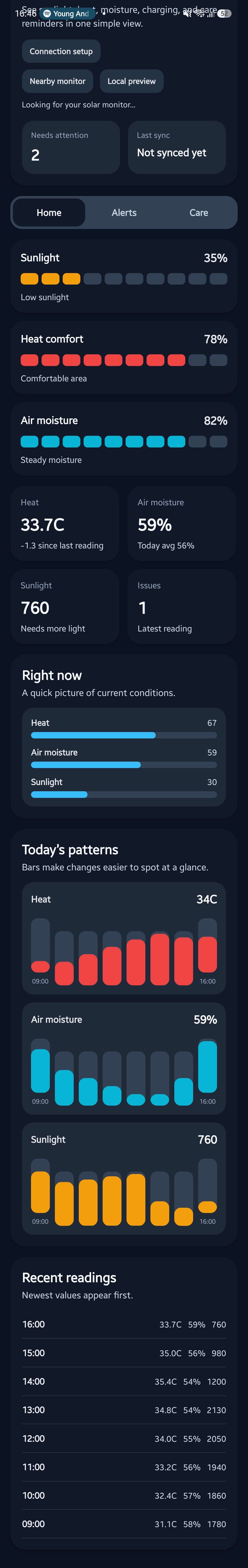
Mobile app which shows all data collected and acts as a control station and dashboard as well
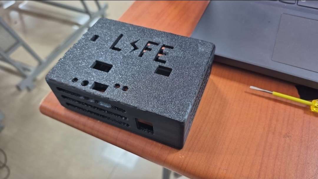
Final Product Image
.png)
Youtube Video
https://www.youtube.com/watch?v=IF7ObpHcfu4
GitHub Repository
https://github.com/Shubham-Khandelwal1/LIFE---ElectronicsWings-Challenge
please check the github repo for the full readme explanation
Code Snippets
Here is the core logic used in our Python-based simulator and hardware bridge to calculate real-time peer-to-peer energy routing when a node detects a surplus:
python
# Extract from useSystemState.js / Python controller

# Determine if we should share surplus energy with neighbors

hardware_surplus = hardware.p_generated - hardware.p_demand

share_load = len(deficits) > 0 and hardware_surplus > 2.0 and hardware.soc > 0.35


if share_load:

    hardware.route = 'GRID'

    hardware.relay_grid = True

    # Divide surplus equally among nodes in deficit

    share_amount = min(hardware_surplus, sum(max(0, n.p_demand - n.p_generated) for n in deficits))

    hardware.energy_flow = share_amount

    for node in deficits:

        node.energy_flow = -min(node.p_demand - node.p_generated, share_amount / len(deficits))

else:

    hardware.route = 'BATTERY'

    hardware.relay_grid = False