Description :
Basically in this project, we protect the writing data in serial EEPROM. Here we use the two different MCU, first one is the 8051 which store the data in EEPROM and second one is the Arduino UNO which read the data from the same EEPROM which already store the data using 8051 MCU but Arduino uno don't overwrite the new data because we have to give the writing protection.
I2C Compatible serial EEPROM (AT24C32) :
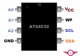
- AT24C32 is the 32KB serial EEPROM, which communicate through the I2C protocol. Here A0,A1,A2 is the adress pin, SDA is the serial data pin which connected to the SDA pin of microcontroller . SCL is the serial clock pin which connected to the SCL pin of the MCU. WP is one of the most important pin which is Write protection pin, later explain in detail.
- You already know I2C based device has it's own address, This address is the 7 bit address and 8 bit is the read or write bit using this address we access the IC and using this address we write and read data from the EEPROM.
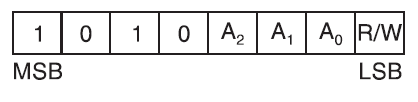
- Here we connect the A2, A1, A0 to the GND pin.
- Write address --> 0xA0
- Read address --> 0xA1
WP pin in EEPROM :
- WP stand for Write protection pin, If this pin is not connected to the vcc that mean protection is disable and user add the new data in eeprom and also read the data from the eeprom.
- If WP pin is connected to the VCC that mean Protection is enable and user do not write the new data in eeprom but read the from the eeprom.
8051 writing data to the EEPROM :
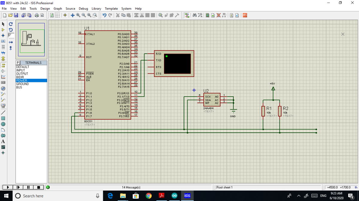
- This is the schematic diagram of the 8051 with serial EEPROM, Important thing is that WP is not connected to the VCC that mean protection is disable. user add the new data to the serial eeprom.
Code of 8051 write data to EEPROM :
#include<reg51.h>
#include<string.h>
#include<INTRINS.h>
#include<delay.h>
#include<I2C.h>
#include<UART.h>
unsigned char x,
name[]="SAVAN";
unsigned int i;
void read_eeprom(void);
void main()
{
	uart_init(0xFA);  //4800 baud rate

    write_eeprom();
	while(1)
	{
		read_eeprom();
		delay(500);
		tx(0x0a);  // for new line in UART
	}
}
void write_eeprom(void)
{
	start();
	write(0xA0);  // Device address
	write(0x00);  // MSB address
	write(0x00);  // LSB address
	for (i=0; i<5; i++)
	{
		write(name[i]);  // write the data to the EEPROM
	}
	stop();
}
void read_eeprom(void)
{
	start();
	write(0xA0);
	write(0x00);
	write(0x00);

	start();
	write(0xA1);  // reading address
	for (i=0; i<5; i++)
	{
		x=read();
		tx(x);
		delay(10);
		ack();
	}
	nack();
	stop();
}
- Finally load the program to the 8051 MCU and show the result .
Schematic of Arduino with EEPROM
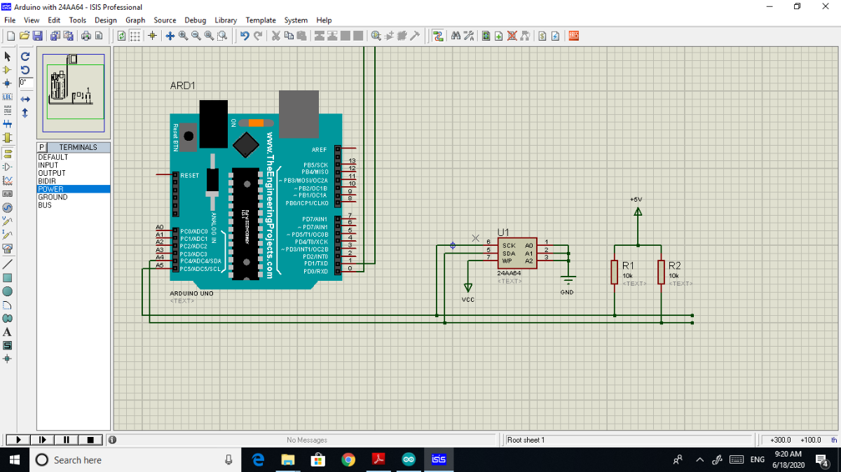
- After processing with 8051 connect the same EEPROM with the Arduino UNO MCU.
- But one of the most important thing is that WP pin connect to the VCC which enable the protection that mean we do not write the new data to the this EEPROM but reading the old data which is store from the 8051 MCU.
Code of Arduino read data from EEPROM which is store from 8051 :
#include<Wire.h>
#define AT24C64 (0xA0>>1)
  // Device address arduino take 7bit address
void setup()
{
  Wire.begin(); // start the I2C
  Serial.begin(9600);
  tx();
}
void loop()
{
  rx();
  delay(500);
}
void tx()
{
  Wire.beginTransmission(AT24C64);
  Wire.write(0x00);   // high address
  Wire.write(0x00);   // low address
  Wire.write('S');
  Wire.write('H');
  Wire.write('R');
  Wire.write('E');
  Wire.write('E');
  Wire.endTransmission();
}
void rx(void)
{
  Wire.beginTransmission(AT24C64);
  Wire.write(0x00);
  Wire.write(0x00);
  Wire.endTransmission();

  Wire.requestFrom(AT24C64,5);
  while(Wire.available())
  {
  char x=Wire.read();
  Serial.print(x);
  delay(10);
  }
  Serial.println();
}
- Show the care fully code, here write the new data which is "SHREE" but when upload sketch then this data doesn't write and only read the old data which is store from the 8051 MCU.
- Finally upload the sketch.......
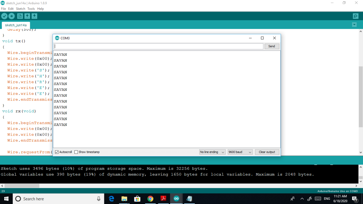
- So using this way protect the data.
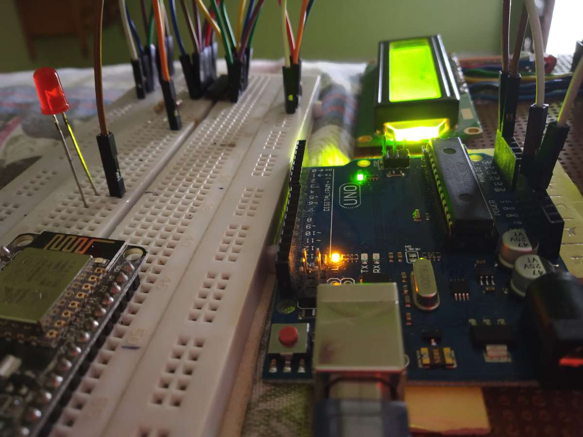
- Hardware setup.