CNG Multi-Device Sale Tracker: Complete Build Guide
What you'll build: A real-time IoT system that connects CNG (Compressed Natural Gas) fuel dispensers to a cloud dashboard. Each dispenser gets an ESP32 that reads sale data over RS-485 Modbus, accepts vehicle number input via a 4×4 keypad, shows status on a 16×2 LCD, and POSTs every completed sale to a Node.js backend. A React dashboard gives operators a live view of all dispensers, vehicle tracking, and daily/weekly/monthly reports.
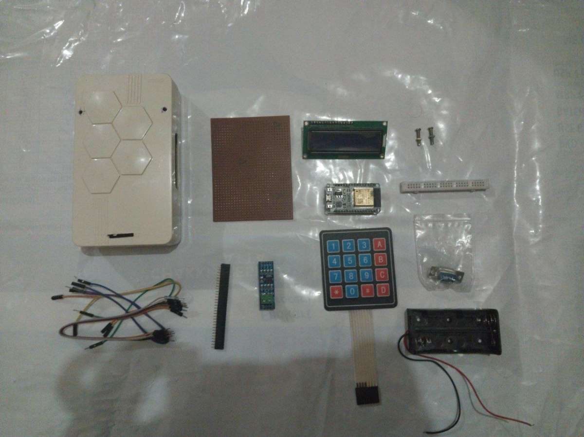
Step 1 — Parts List
| Component | Qty |
| ESP32 Dev Board | 1 |
| RS-485 Module | 1 |
| 4×4 Matrix Keypad | 1 |
| 16×2 LCD Display | 1 |
| RS-485 cable | 1 |
| USB-A to Micro-USB | 1 |
| Dupont jumper wires | |
| Breadboard or PCB | 1 |
| 5 V power supply | 1 |
| Project enclosure box | 1 |
For the Server (one-time)
| Component | Notes |
| WiFi router | All ESP32 units must reach the same network as the server |
| PC / Laptop | Running Node.js backend (or a Raspberry Pi / cloud VM) |
| MongoDB | Local install or MongoDB Atlas free tier |
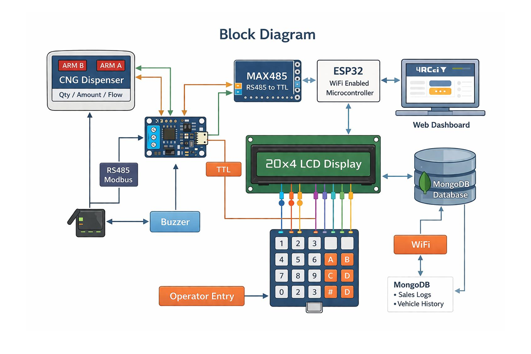
Step 2 — System Architecture
Understanding the data flow will save you debugging time later.
How a sale is recorded (step-by-step data flow)
1. Operator presses `*` on the keypad → ESP32 enters vehicle number mode.
2. Operator types the vehicle plate using multi-tap (Nokia phone style) and presses `#`.
3. ESP32 shows "Dispensing…" and starts polling the dispenser via Modbus RS-485 every 50 ms.
4. When the dispenser finishes filling, it sets Modbus register `REG_TX_STATUS = 1`.
5. ESP32 reads quantity (kg), amount (₹), and flow rate from Modbus registers.
6. ESP32 POSTs a JSON record to `POST /api/sales` over WiFi.
7. Backend saves to MongoDB and pushes a real-time update to all open dashboards via SSE.
8. LCD shows "Sent! GJ01AB1234 / Next vehicle…" for 2 seconds, then resets.
Step 3 — Hardware Assembly
3.1 — Prepare the ESP32
1. Plug the ESP32 into your breadboard so the two rows of pins straddle the center gap.
2. Leave at least 3 rows of free breadboard above and below the ESP32 for jumper wires.
3. If your ESP32 doesn't come with headers soldered, solder 2.54 mm male headers now.
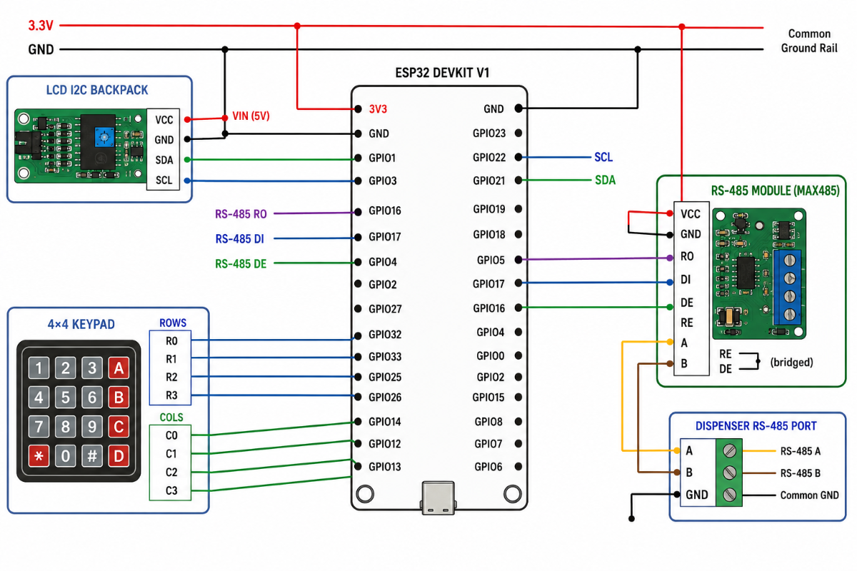
3.2 — Wire the RS-485 Module
The RS-485 module (MAX485 / SP3485) translates the ESP32's TTL UART signals to the differential A/B signals used by Modbus.
| RS-485 Module Pin | ESP32 |
| VCC | 3.3 V |
| GND | GND |
| RO (Receiver Out) | GPIO 16 (Serial2 RX) |
| DI (Driver In) | PIO 17 (Serial2 TX) |
| DE (Driver Enable) | If auto-direction: bridge to RE. If manual: GPIO 4 |
| RE (Receiver Enable) | Bridge to DE (tie them together) |
- | A | Dispenser RS-485 terminal A
- | B | Dispenser RS-485 terminal B
Auto-direction modules: (like the widely available blue MAX485 breakout) have DE and RE
already bridged internally. Just connect RO→GPIO16, DI→GPIO17, and the A/B pair to the
dispenser. Set `RS485_DE_PIN -1` in `modbus_test.ino` if testing.
Wiring the A/B cable to the dispenser: Locate the Modbus RS-485 port on your
dispenser (usually labeled "RS-485", "COM", or "Modbus" on the terminal strip).
Connect A→A, B→B, and share a GND wire between the ESP32 ground and the dispenser
chassis ground to prevent noise.
3.3 — Wire the 16×2 I2C LCD
The LCD uses only 4 wires thanks to the I2C backpack.
| CD I2C Backpack Pin | ESP32 |
| VCC | VIN pin |
| GND | GND |
| SDA | GPIO 21 |
| SCL | GPIO 22 |
- If the display shows all black squares after power-on, turn the contrast pot on the
- back of the I2C backpack. If `0x27` doesn't work, try `0x3F` in `config.h`.
3.4 — Wire the 4×4 Matrix Keypad
The keypad has 8 pins — 4 rows and 4 columns. Pin 1 is usually marked with a triangle.
| Keypad Pin | ESP32 |
| Row 0 | GPIO 13 |
| Row 1 | GPIO 12 |
| Row 2 | GPIO 14 |
| Row 3 | GPIO 27 |
| Col 0 | GPIO 26 |
| Col 1 | GPIO 25 |
| Col 2 | GPIO 33 |
| Col 3 | GPIO 32 |
- Pin 1 is the leftmost pin when the keypad faces you with keys visible.
- The row pins are typically the first 4, column pins are the last 4.
- Check your keypad's datasheet if unsure — a multimeter in continuity mode will confirm which pins short when you press a key.
3.5: Power
- Power the ESP32 via its USB port during development and testing.
- In the field, use a 5 V / 2 A DC supply connected to the VIN and GND pins,
- or use a USB wall adapter with a permanently attached cable.
- The LCD and keypad draw minimal current the ESP32's own regulators can supply them.
Step 4 — Wiring Diagram & Pin Reference
Step 5: Test the Hardware Before Soldering
Always verify each component with the dedicated test sketches before you solder everything into a permanent enclosure. This saves hours of debugging.
5.1: Install the Arduino IDE and ESP32 Board Support
1. Download Arduino IDE 2.x.
2. Open File → Preferences and add this URL to "Additional Boards Manager URLs":
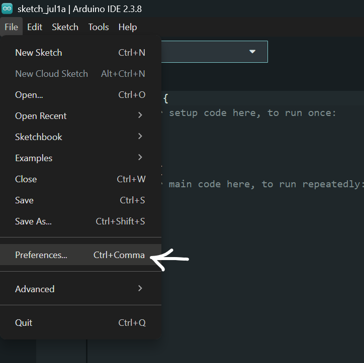
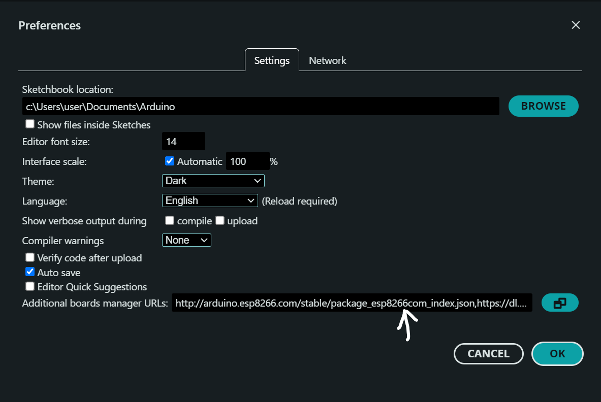
https://raw.githubusercontent.com/espressif/arduino-esp32/gh-pages/package_esp32_index.json
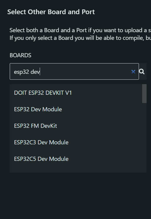
3. Go to Tools → Board → Boards Manager, search for `esp32`, and install
"esp32 by Espressif Systems".
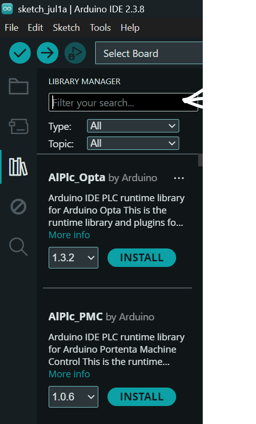
4. Install required libraries via Sketch → Include Library → Manage Libraries:
`Keypad` by Mark Stanley & Alexander Brevig
`LiquidCrystal I2C` by Frank de Brabander
5.2 — Test the LCD
1. Open `lcd_test.ino` in Arduino IDE.
2. Select your board: Tools → Board → ESP32 Dev Module.
3. Select the correct COM port under Tools → Port.
4. Click Upload (→ arrow icon).
5. Expected result: LCD backlight turns on, Row 0 shows "LCD Test OK",
Row 1 shows "Hello CNG!".
6. If nothing displays: check SDA/SCL wiring, adjust contrast pot, try I2C address `0x3F`.
5.3 — Test the Keypad
1. Open `firmware/test_scripts/keypad_test.ino`.
2. Upload to the ESP32.
3. Open Serial Monitor at 115200 baud.
4. Press each of the 16 keys one at a time.
5. Expected result: Each key press prints the correct character
(`1 2 3 A / 4 5 6 B / 7 8 9 C / * 0 # D`).
5.4 — Test the Modbus RS-485 Connection to the Dispenser
1. Open `modbus_test.ino`.
2. Upload and open Serial Monitor at 115200 baud.
3. Find the baud rate: Press `b` → the tool tries 1200/2400/4800/9600/19200/38400/57600.
Note which baud gets a "RESPONSE RECEIVED ✓".
4. Find the slave address: Update `MODBUS_BAUD` at the top of the sketch with the
found value, re-upload, then press `a` → scan addresses 1–32.
5. Scan registers: Press `s` → all non-zero registers print.
Then do a test dispense (fill a few kg), press `s` again.
The registers that changed are your transaction registers.
Known presets already included in config.h:
- Kranti (baud 9600), Adani (baud 19200), NeoGas/Elgi (baud 9600),
- Bennett/Wayne (baud 38400). If you have one of these, just uncomment the
- right `#define DISPENSER_XXX` line — no register scanning needed.
5.5 — Test WiFi + Backend Connectivity
1. Open `wifi_api_test.ino`.
2. Fill in `WIFI_SSID`, `WIFI_PASSWORD`, and `API_BASE_URL` at the top.
3. Upload and open Serial Monitor at 115200 baud.
4. On boot it runs 5 tests automatically:
- Test 1: Backend reachable (expects HTTP 200)
- Test 2: Device found in registry
- Test 3: POST a synthetic sale (expects HTTP 201)
- Test 4: Heartbeat PATCH (expects HTTP 200)
- Test 5: Retry logic with a bad URL
Run this test after Step 6 (backend setup) so the API is running before you test.
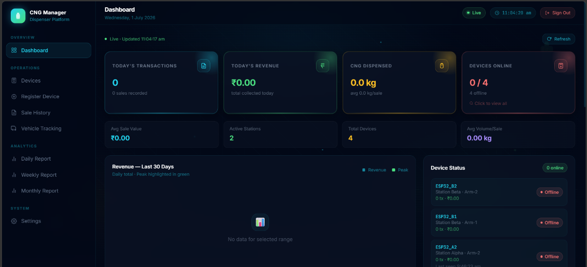
Step 6: Dashboard Pages Overview
Step 7 — Firmware Configuration & Flash
7.1 — Understand the config.h File
Every ESP32 unit is flashed with the **same sketch but a different `config.h`. The pre-built per-device configs are in `firmware/devices/`:
firmware/
devices/
ESP32_A1/config.h ← Station Alpha, Arm 1
ESP32_A2/config.h ← Station Alpha, Arm 2
ESP32_B1/config.h ← Station Beta, Arm 1
ESP32_B2/config.h ← Station Beta, Arm 2
esp32_dispenser_client/
config.h ← master template (edit this for flashing)
esp32_dispenser_client.ino
7.2: Configure for Your First Dispenser
Open `firmware/esp32_dispenser_client/config.h` and work through the four steps marked inside the file:
Step 1: Select your dispenser brand (uncomment exactly one):
#define DISPENSER_GENERIC // default — fill in custom map
Step 2: Set the unique device ID (change for every unit):
#define DEVICE_ID "ESP32_A1" // ← MUST match what you seeded in MongoDB
Step 3: Set the Modbus slave address:
#define MODBUS_ADDR 1 // ← use 'a' scan from modbus_test.ino to find this
Step 4: Set WiFi and API (same for all units at one station):**
#define WIFI_SSID "YourStationWiFi"
#define WIFI_PASSWORD "YourPassword"
#define API_BASE_URL "http://192.168.1.100:5000" // ← your server's LAN IP
If you chose `DISPENSER_GENERIC`, also fill in the register addresses you found in Step 5.4:
#define MODBUS_BAUD 9600 // ← from baud scan
#define REG_TX_STATUS 0x0000 // ← register that = 1 after a fill
#define REG_QTY_HI 0x0001 // ← quantity high word
#define REG_QTY_LO 0x0002 // ← quantity low word
#define REG_AMT_HI 0x0003 // ← amount high word
#define REG_AMT_LO 0x0004 // ← amount low word
#define MODBUS_REG_COUNT 15 // ← total regs to read in one FC03 call
7.3: Flash the Firmware
1. Connect the ESP32 to your PC via USB.
2. In Arduino IDE:
- Tools → Board → select "ESP32 Dev Module"
- Tools → Port → select the COM port for your ESP32 (Windows: `COM3`, `COM4`, etc. — check Device Manager if unsure. macOS/Linux: `/dev/tty.SLAB_USBtoUART` or `/dev/ttyUSB0`)
- Tools → Upload Speed → `921600` (or lower if uploads fail)
3. Click Upload (→ arrow).
4. You may need to hold the **BOOT** button on the ESP32 while upload starts
(only required on some boards without auto-reset circuitry).
7.4 — Verify on Boot
Open Serial Monitor at 115200 baud immediately after flashing.
You should see: CNG Dispenser Client v4.0
Device : ESP32_A1
Modbus : addr=1
WiFi : YourStationWiFi
API : http://192.168.1.100:5000
[WiFi] Connecting to "YourStationWiFi"...
[WiFi] Connected IP=192.168.1.105
[Device] Fetching _id from http://192.168.1.100:5000/api/devices/lookup/ESP32_A1
[Device] Resolved _id=64f3a8c9b2e1234567890abc
[Heartbeat] online code=200
- And the LCD shows: `CNG Ready [WiFi]` / `Press * to start`
Step 8 — Register the Devices in the Dashboard
The ESP32 firmware looks up its own MongoDB `_id` by calling`GET /api/devices/lookup/{DEVICE_ID}`. This only works if the device document already exists in the database.
8.1 — Check Seeded Devices
The `seed_devices.js` script (Step 6.5) already created 4 devices:
`ESP32_A1`, `ESP32_A2`, `ESP32_B1`, `ESP32_B2`.
Verify them in the Devices page of the dashboard, or via the API: curl http://localhost:5000/api/devices
8.2 — Add a Custom Device
If your dispenser has a different ID than the seeded defaults, add it via the dashboard
Devices page (click "+ Add Device") or with the API:
curl -X POST http://localhost:5000/api/devices \
-H "Content-Type: application/json" \
-d '{
"deviceId": "ESP32_C1",
"station": "Station Charlie",
"arm": "Arm 1",
"description": "North pump island"
}'
The `deviceId` here must exactly match `DEVICE_ID` in `config.h`.
8.3 — Confirm Device Goes Online
After flashing and connecting to WiFi, the ESP32 sends a heartbeat PATCH every 20 seconds.
Within 20 seconds of boot, the device card in the dashboard should show a green "online" badge.
Step 9: Connect Everything: Full System Test
With hardware wired, backend running, frontend open, and firmware flashed, run a complete end-to-end test to confirm the entire pipeline works.
9.1 — Simulate a Sale from the Keypad
1. On the ESP32 keypad, press `*` → LCD shows `Enter Veh No: / >_`
2. Type a vehicle number using multi-tap:
- Press `4` once → `4`
- Press `5` twice → `5`, `5J` → wait 1.5 s to commit `J`
- Press `0` once → `0`
- Press `1` once → `1`
- Continue until you have e.g., `GJ01AB1234`
- Press `#` to confirm
3. LCD shows `Dispensing… / Veh:GJ01AB1234`
4. Trigger a Modbus transaction on your dispenser (do a short fill, or use
`modbus_test.ino` → press `w` to write `REG_TX_STATUS = 0` after a real fill to
simulate acknowledgment)
5. LCD shows `Sent! 5.20kg / Rs442 GJ01AB1234`
9.2 — Verify in the Dashboard
1. Open the Sale History page — the new sale should appear at the top.
2. Open the Dashboard: today's sale count and revenue should be updated.
3. Open the Vehicle Tracking page and search for `GJ01AB1234` — the fill history
should show the record.
Step 10 — Scaling to Multiple Dispensers
Each additional dispenser arm gets its own ESP32 unit. The process is identical to
10.1 — Create a Per-Device config.h
Copy `firmware/esp32_dispenser_client/config.h` and change only:
#define DEVICE_ID "ESP32_A2" // ← unique ID for this unit
#define MODBUS_ADDR 1 // ← this dispenser's Modbus address
// (usually 1 per dispenser, since each
// ESP32 has its own RS-485 bus)
WiFi credentials and `API_BASE_URL` stay the same across all units.
- The pre-made configs in `firmware/devices/` are ready to use:
- `firmware/devices/ESP32_A1/config.h` | ESP32_A1 | Alpha | 1 |
- `firmware/devices/ESP32_A2/config.h` | ESP32_A2 | Alpha | 2 |
- `firmware/devices/ESP32_B1/config.h` | ESP32_B1 | Beta | 1 |
- `firmware/devices/ESP32_B2/config.h` | ESP32_B2 | Beta | 2 |
10.2 — Each Unit is Independent
- Each ESP32 has its own RS-485 connection to its own dispenser.
- All units share the same WiFi and backend URL.
- The backend uses `deviceId` to distinguish sales from different arms.
- The dashboard shows all devices in a single unified view.
10.3 — RS-485 Bus Topology
Each ESP32 connects to **one dispenser only** (point-to-point). This is the simplest and most reliable topology. If your dispenser manufacturer already daisy-chains multiple dispenser heads on one RS-485 bus (common in 2-arm dispensers), you can use Modbus addresses 1 and 2 on the same RS-485 pair, but you'll need only one ESP32 with a modified sketch — contact the dispenser manufacturer for the register map in that case.
Step 11 — Troubleshooting
LCD shows nothing / all black squares
- Turn the small blue contrast potentiometer on the back of the I2C backpack.
- Verify SDA→GPIO21, SCL→GPIO22.
- Try changing `LCD_I2C_ADDR` from `0x27` to `0x3F` in `config.h`.
- Run an I2C scanner sketch to find the actual address.
Keypad keys not registering or wrong characters
- Re-check the row/column GPIO assignments against the physical keypad ribbon.
- Use a multimeter in continuity mode: pressing a key should short one row pin to one column pin.
- Pin 1 of the keypad (marked with a dot or arrow) is row 0.
Modbus: "No valid response" in modbus_test.ino
- Check A/B polarity — swap them if needed.
- Verify the RS-485 module DE/RE pins are bridged.
- Confirm the dispenser is powered and its Modbus port is active.
- Run baud scan (`b`) — your dispenser may use 19200 or 38400, not 9600.
- Check the dispenser manual for the RS-485 terminal location — some models label it "COM" or have it inside a locked service panel.
ESP32 shows "CNG Ready[NoWiFi]" and never connects
- Confirm SSID and password in `config.h` are correct (case-sensitive).
- Check the ESP32 is within range of the access point.
- ESP32 only supports 2.4 GHz WiFi — if your router is 5 GHz only, it won't connect.
- If you changed `WIFI_RECONNECT_INTERVAL_MS`, ensure it's not set too short.
Serial Monitor shows "Device _id not found" or fetch fails
- Confirm the backend is running and reachable at `API_BASE_URL`.
- Verify the device was seeded: `node scripts/seed_devices.js`.
- Check the `DEVICE_ID` in `config.h` exactly matches the `deviceId` in MongoDB (case-sensitive: `ESP32_A1` ≠ `esp32_a1`).
- Test with `wifi_api_test.ino` → Test 2 will report if the device is missing.
Sales not appearing in the dashboard
- Check the backend terminal for incoming POST requests — each sale should print: `[hh:mm:ss] POST /api/sales`
- Confirm the POST returns HTTP 201 (check Serial Monitor: `[Flush] OK veh=...`).
- If HTTP 4xx, the `deviceId` in the POST body may not match any registered device.
- Refresh the dashboard — the SSE live update may not have connected; a manual refresh will always show the latest data from MongoDB.
Backend won't start — "MongoServerError: connect ECONNREFUSED"
- Make sure MongoDB is running: `mongod --dbpath /data/db` (Linux/Mac) or start the MongoDB service in Windows Services.
- If using Atlas, confirm the `MONGO_URI` in `.env` is the full Atlas connection string including username, password, and cluster hostname.
DEVICE_ID is not defined compile error
- This means you are compiling the main sketch without `config.h` present in the same folder. Make sure both `esp32_dispenser_client.ino` and `config.h` are in the same directory, and that directory is what you opened in Arduino IDE.