
ThermoGuard: Smart Temperature Monitoring & Alert System
ThermoGuard is an IoT-enabled Smart Temperature Monitoring and Alert System designed to monitor, analyze, and protect temperature-sensitive environments in real time. The system utilizes an ESP32 microcontroller, DS18B20 temperature sensor, 16×2 LCD display, and buzzer alarm to provide intelligent temperature monitoring through a wireless web dashboard.
Unlike conventional thermometers that only display temperature values, ThermoGuard continuously compares live temperature readings against predefined safe ranges and automatically generates alerts whenever abnormal conditions are detected.
The project is designed for applications such as healthcare monitoring, food storage, greenhouses, laboratories, fish tanks, server rooms, and smart homes.
Components Required:
| Component | Quantity |
|---|---|
| ESP32 Development Board | 1 |
| DS18B20 Temperature Sensor | 1 |
| LCD 16×2 I2C Display | 1 |
| Active Buzzer | 1 |
| 4.7kΩ Resistor | 1 |
| Breadboard | 1 |
| Jumper Wires | As Required |
Hardware Description
ESP32:
- ESP32 acts as the main controller of the system. It reads temperature data from the DS18B20 sensor, processes it, updates the LCD display, hosts the web dashboard, and controls the buzzer alarm.
DS18B20 Temperature Sensor:
- The DS18B20 is a digital temperature sensor capable of providing accurate temperature measurements over a wide operating range.
LCD Display:
- The 16×2 I2C LCD provides real-time temperature readings and system status information.
Active Buzzer:
- The buzzer generates audible alerts whenever temperature exceeds or falls below the predefined limits.
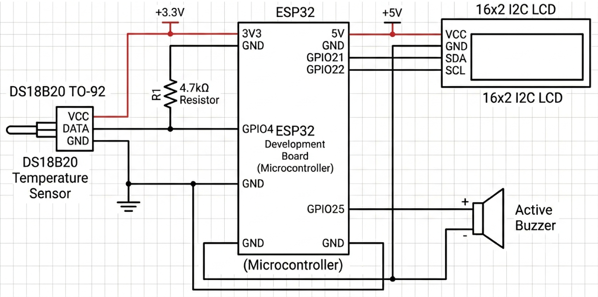
Circuit Diagram
Working Principle
The system continuously measures temperature using the DS18B20 sensor. The measured value is transmitted to the ESP32 microcontroller for processing.
The ESP32 performs the following tasks:
- Displays temperature on the LCD.
- Updates the web dashboard.
- Compares temperature with predefined safety limits.
- Detects abnormal conditions.
- Activates the buzzer during alert conditions.
Users can access the dashboard through a smartphone browser connected to the same WiFi network.
Monitoring Categories
The dashboard allows users to select different monitoring categories:
| Category | Minimum Temperature | Maximum Temperature |
|---|---|---|
| Human Body | 36.1°C | 37.2°C |
| Room | 20°C | 26°C |
| Drinking Water | 10°C | 25°C |
| Cold Drink | 1°C | 5°C |
| Milk Storage | 1°C | 4°C |
| Refrigerator | 2°C | 5°C |
| Fish Tank | 22°C | 28°C |
| Greenhouse | 18°C | 30°C |
| Server Room | 18°C | 24°C |
Alert System
Normal Condition:
When the temperature remains within the safe range:
- Dashboard displays NORMAL.
- LCD displays NORMAL.
- Buzzer remains OFF.
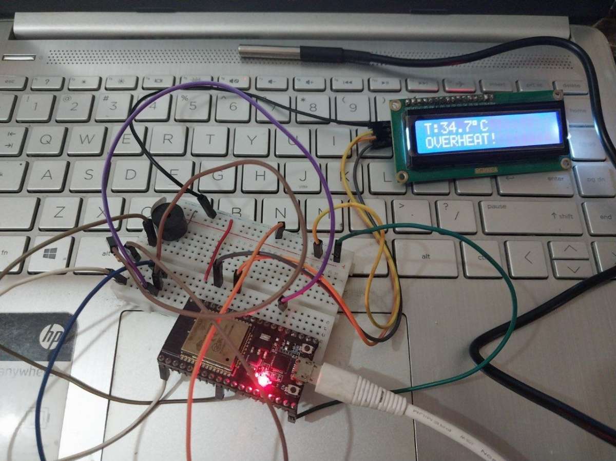
Overheat Alert:
When temperature exceeds the maximum safe limit:
- Dashboard displays OVERHEAT ALERT.
- LCD displays OVERHEAT.
- Buzzer activates automatically.
Low Temperature Alert:
When temperature falls below the minimum safe limit:
- Dashboard displays LOW TEMP ALERT.
- LCD displays LOW TEMP.
- Buzzer activates automatically.
Steps to Build the Project
Step 1: Gather Components
Collect all required components:
- ESP32
- DS18B20
- LCD 16×2 I2C
- Active Buzzer
- Breadboard
- Jumper Wires
Step 2: Connect DS18B20
| DS18B20 Pin | ESP32 Pin |
|---|---|
| VCC | 3.3V |
| GND | GND |
| DATA | GPIO4 |
Note: Connect a 4.7kΩ resistor between DATA and 3.3V.
Add a 4.7kΩ pull-up resistor between DATA and 3.3V.
Step 3: Connect LCD
| LCD Pin | ESP32 Pin |
|---|---|
| VCC | 5V |
| GND | GND |
| SDA | GPIO21 |
| SCL | GPIO22 |
Step 4: Connect Buzzer
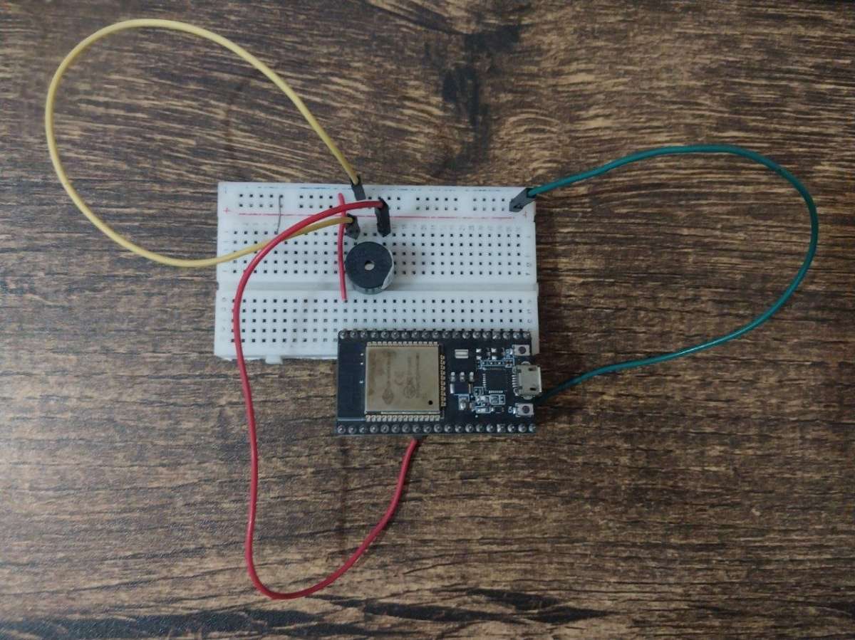
| Buzzer Pin | ESP32 Pin |
|---|---|
| Positive (+) | GPIO25 |
| Negative (-) | GND |
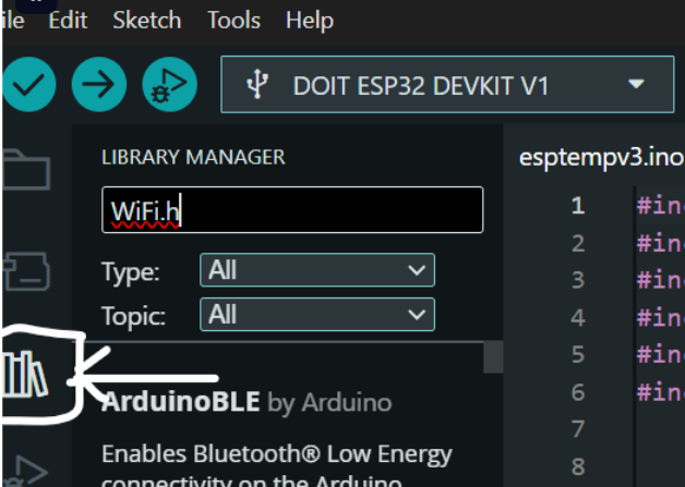
Step 5: Install Required Libraries
Install:
- WiFi.h
- WebServer.h
- OneWire.h
- DallasTemperature.h
- Wire.h
- LiquidCrystal_I2C.h
Step 6: Upload the Code
Upload the ThermoGuard firmware to the ESP32 using Arduino IDE.
.png)
Step 7: Connect to WiFi
Update:
const char* ssid = "YourWiFi";
const char* password = "YourPassword";
Upload the program.
Step 8: Open Dashboard
Open Serial Monitor.
Find:
192.168.x.x.png)
Enter the IP address into a browser.
Example:
http://192.168.1.105.png)
Step 9: Select Monitoring Category
Choose:
- Room
- Human Body
- Refrigerator
- Fish Tank
- Greenhouse
etc.
The system automatically loads safe temperature limits.
Step 10: Test Alerts
Apply heat or cooling to the sensor.
Observe:
- LCD updates
- Dashboard updates
- Buzzer activation
- Alert messages
.png)