
In this project, we have developed a 6-DoF Robotic Arm that can recognise different kinds of objects based on their material type and sort them accordingly. This is done with the help of fine-tuned YOLO11 with precise servo control to create an automated waste management solution.
DigiKey My-List
Here are the components we used for this project. I’ve created a custom DigiKey My-List that includes the manufacturer part numbers for each item. You can view the complete list using the link below.
https://www.digikey.in/en/mylists/list/JQI803LV04?cur=INR
- Arduino R4 wifi
- MG995 (Metal Gear) Servo Motor
- SG90 Servo Motor
- PCA9685 16-Channel Servo Driver
- Ultrasonic Sensor
- ESP32 CAM Module (with
- 5 V 10 A SMPS Power Supply
- Jumper Wires
- Breadboard
- 3D-Printed Parts
Components Used
Arduino R4 wifi
.jpeg)
The Arduino R4 wifi is the central brain. It takes the classification data from YOLO and distance measurements from the ultrasonic sensor. It then uses inverse kinematics to calculate and send precise motion instructions to all six servo motors, enabling the robotic arm to pick the item and place it in the correct bin.
MG995 (Metal Gear) Servo Motor
The MG995 Servo Motors are used for the Waist , Shoulder and Elbow, as these are the foundational joints that bear the most structural load. They provide a high torque of 9.4 kg/cm.
SG90 Servo Motor
The SG90 Servo Motor powers the Wrist Roll, Wrist Pitch, and Gripper joints of the robotic arm. They are of lighter weight and compact size.
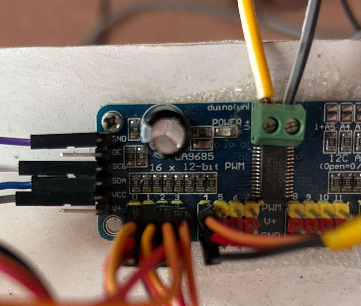
PCA9685 16-Channel Servo Driver
.jpeg)
The PCA9685 16-Channel Servo Driver is an expansion board that allows the Arduino to efficiently control the six servo motors. It uses I2C communication to save pins and is essential for connecting the powerful external 5V 10A supply to the motors, preventing the Arduino from being overloaded.
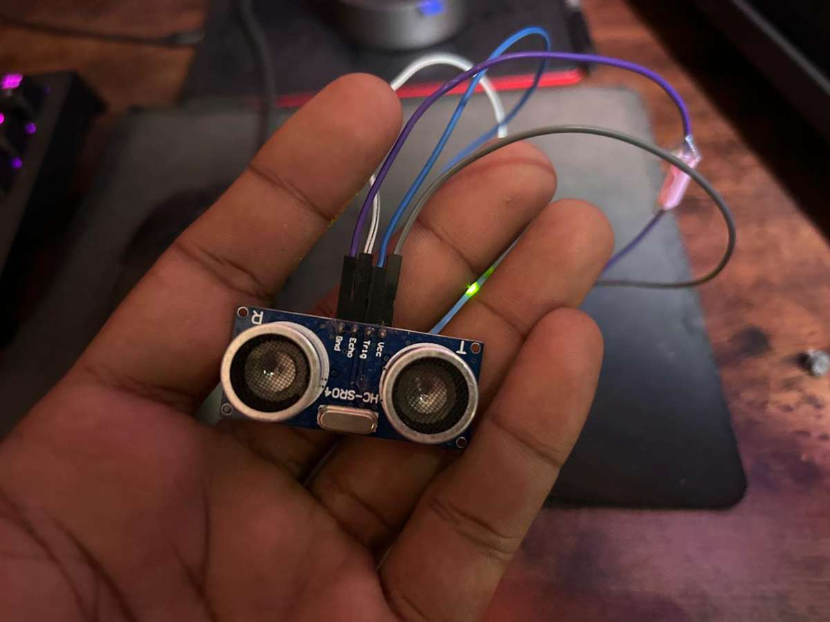
Ultrasonic Sensor
.jpeg)
The Ultrasonic Sensor measures the distance from the robotic arm to the detected object. Provides crucial coordinate data that the Arduino uses for precise kinematics control.
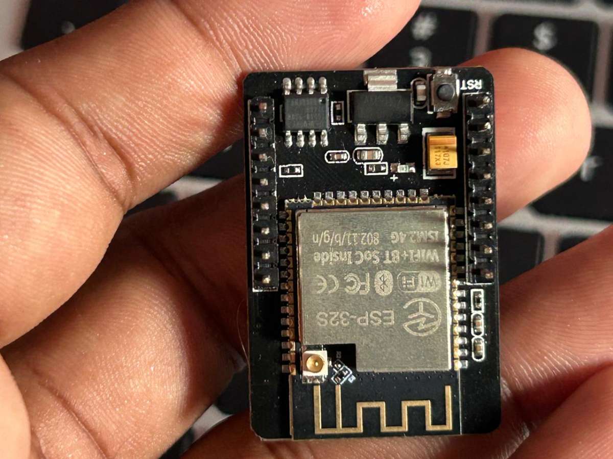
ESP32-CAM Module
.jpeg)
The ESP32-CAM acts as the system's eye, capturing real-time images of the surrounding area for the YOLO model to the process. Equipped with an OV2640 wide-angle lens for a wider field of view, and operates as a low-cost, edge-based vision system.
5V SVMPS Power Supply
.jpeg)
Software Requirements
Python Dependencies
- Python 3.8 or higher
- OpenCV
- Ultralytics YOLO
- NumPy
- PySerial
- Apache Kafka
- Docker
- Nodejs
- React
Arduino Libraries
- Wire.h (built-in)
- ESP32 by Expressif
- Adafruit_PWMServoDriver.h
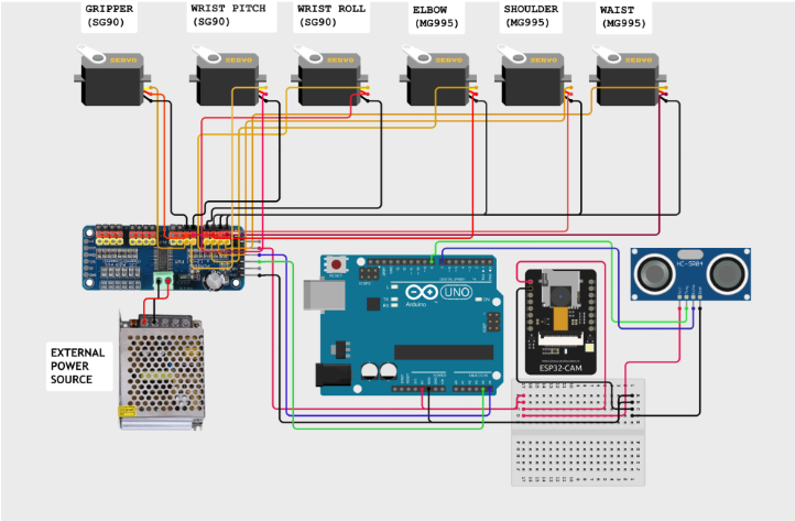
Circuit Diagram
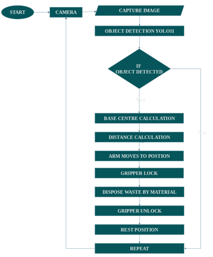
Flow Chart
The program is executed as shown in the flow chart
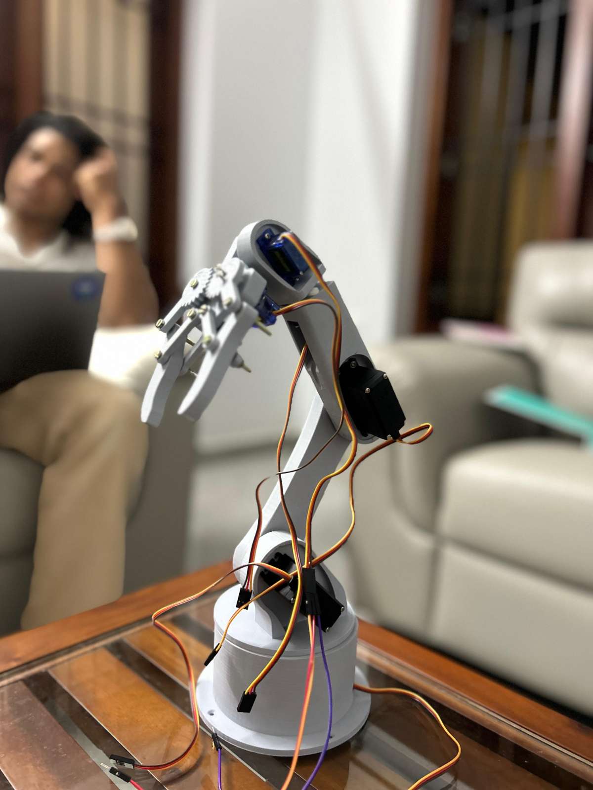
Assembly of Robotic Arm
Assemble the parts of the Robotic Arm and insert motors in the designated parts. STL files for 3D printing are attached below.
Setting up of ESP32-CAM Module
Insert the OV2640 wide-angle lens into the ESP32-Cam module.
To flash the Camera Web Server to the ESP32-CAM using the Arduino IDE, first install the ESP32 board package via the Boards Manager and configure the IDE by selecting "AI Thinker ESP32-CAM" as the board.
Next, open the "CameraWebServer" example sketch, enter your Wi-Fi SSID and password, and specifically enable the correct hardware by uncommenting #defineCAMERA_MODEL_AI_THINKER while ensuring all other camera models are commented out. Finally, select the correct COM port and click "Upload", and press the physical "RESET" button on the board.
Once complete, open the Serial Monitor at a baud rate of 115200 to retrieve the IP address for viewing the camera stream.
Setting up of Ultrasonic Sensor
The Ultrasonic Sensor is set up by connecting its power pins to the Arduino's 5V and GND, and its Trig and Echo pins to digital I/O pins. The Arduino triggers a sound pulse and measures the echo duration to calculate the distance to the object. This measurement provides the essential depth coordinate for the inverse kinematics algorithm, ensuring the robotic arm extends exactly enough to grasp the target.
Assemble the housing of the ESP32-CAM module and Ultrasonic sensor, and mount it on the Robotic Arm.
.jpeg)
.JPG)
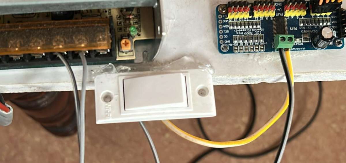
Setting Up The Servo-Driver Board
The connection process begins by ensuring the 5V 10A SMPS is unplugged for safety. The high current output from the SMPS is connected directly to the PCA9685 Servo Driver Board by linking the positive 5V output to the board's V+ terminal and the Ground output to the board's GND terminal. We used a switch here as a fail-safe.
Next, the six servo motors are plugged into the driver board's PWM channel headers, ensuring the signal, power and ground wires of each motor are correctly aligned with the corresponding pins on the board.
Finally, the Servo Driver Board is connected to the Arduino via I2C communication, by connecting the board's SDA pin to the Arduino's SDA pin (A5) and the board's SCL pin to the Arduino's SCL pin (A4), along with a shared GND connection. This Configuration allows the Arduino to command the six motors efficiently while isolating them from the high current draw of the external power supply.
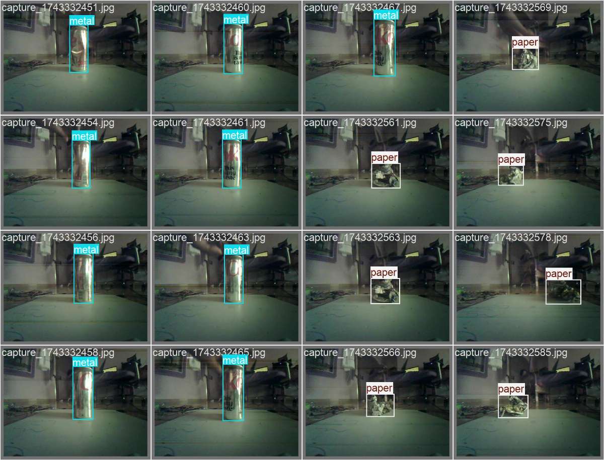
Training YOLO
To train the YOLO model using the Ultralytics framework, we have to organise the custom dataset into the standard YOLO format, where each image has a corresponding text file containing bounding box coordinates and class labels for items like plastic, metal and paper.
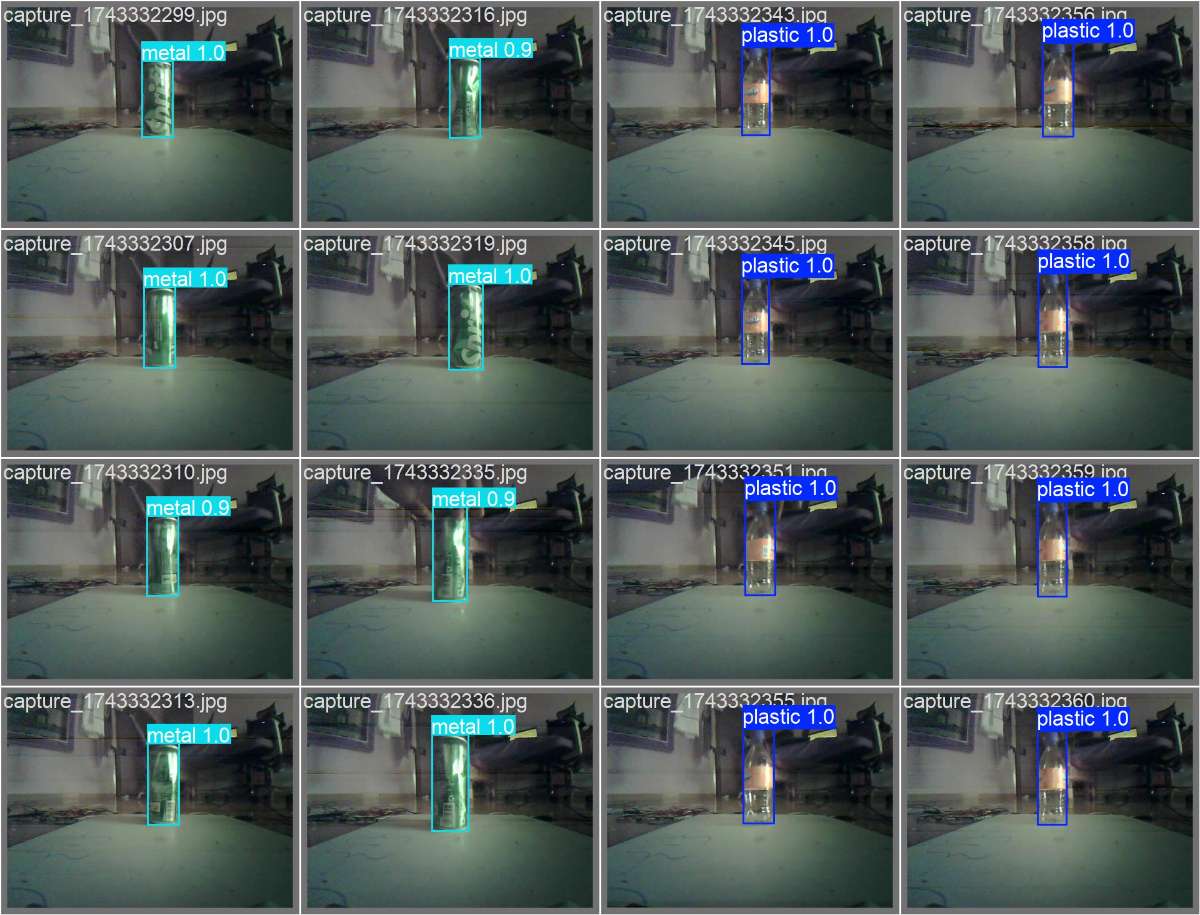
With the environment prepared by installing the "Ultralyrics" library, a pre-trained model such as "yolo11n.pt" is loaded to improve efficiency.
The training is executed using a Python Script, where key parameters like number of epochs, image size and batch size are specified. Over the course of the training epochs, the model iteratively learns features and minimises loss and saves the better weight file that is then deployed to the system for real-time inference.
Dashboard
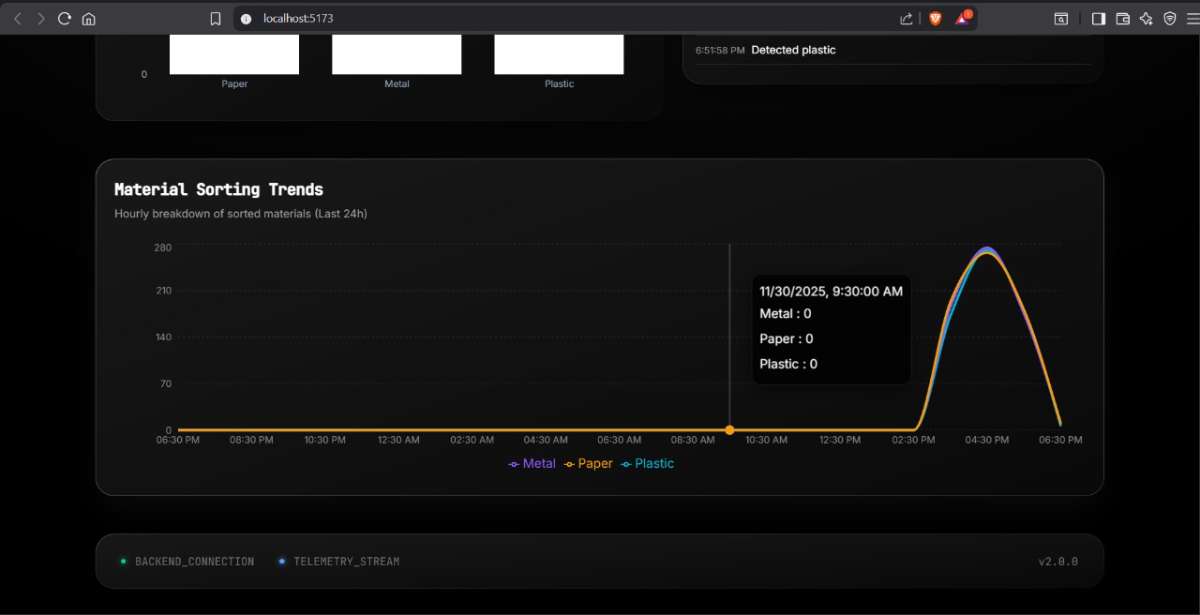
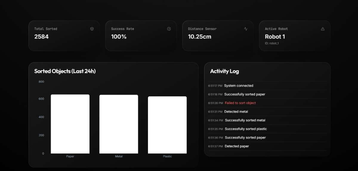
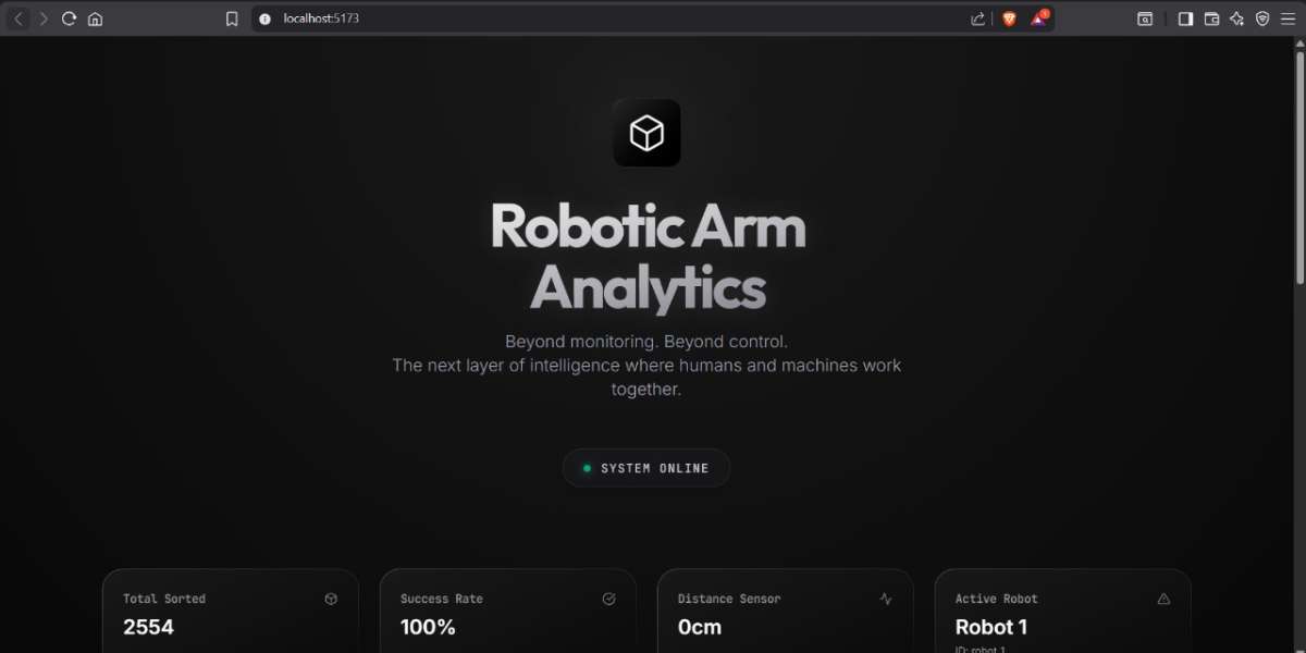
The dashboard is made with ReactJS. This dashboard gives real-time data on the sorted objects, and by using Apache Kafka, data can be moved between systems in real time. it acts as a high-speed stream that streams massive amounts of data like logs, sensor readings etc, instantly in real-time.
The dashboard is industrial-level scalable which can be used in a enivronment with several number of roobts working simulataneously.
Refer github repository for code
LIVE DEMONSTRATION OF SORTING PAPER