




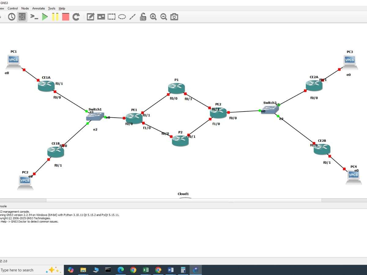
Step 1: Designed the Network Topology
The MPLS network topology was created in GNS3 using Cisco routers. The network consists of Customer Edge (CE), Provider Edge (PE), and Provider (P) routers. GNS3 allows the topology and router configurations to be tested in a simulated environment.
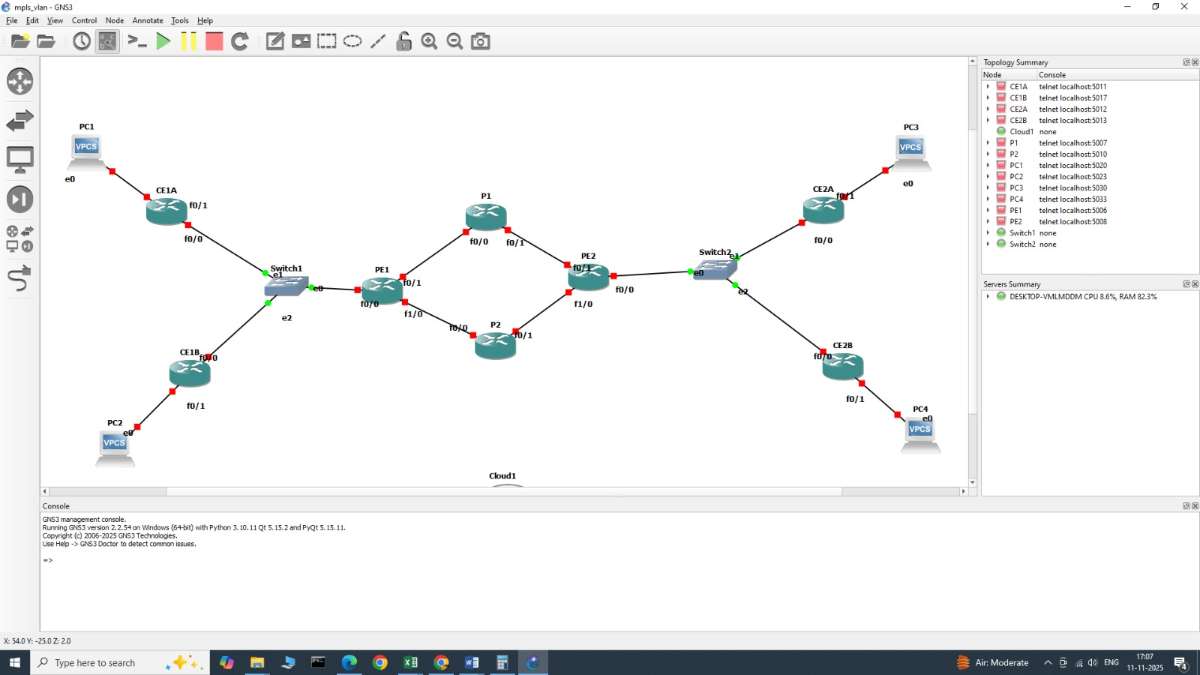
Step 2: Configured IP Addressing
IP addresses were assigned to the router interfaces and loopback interfaces. Connectivity between the routers was verified using the ping command.
Step 3: Configured OSPF Routing
OSPF was configured as the Interior Gateway Protocol to provide connectivity across the MPLS core. OSPF neighbors and routing tables were verified before moving to the next stage.
Step 4: Enabled MPLS and LDP
MPLS forwarding was enabled on the provider routers, and Label Distribution Protocol (LDP) was configured to distribute labels through the MPLS core.
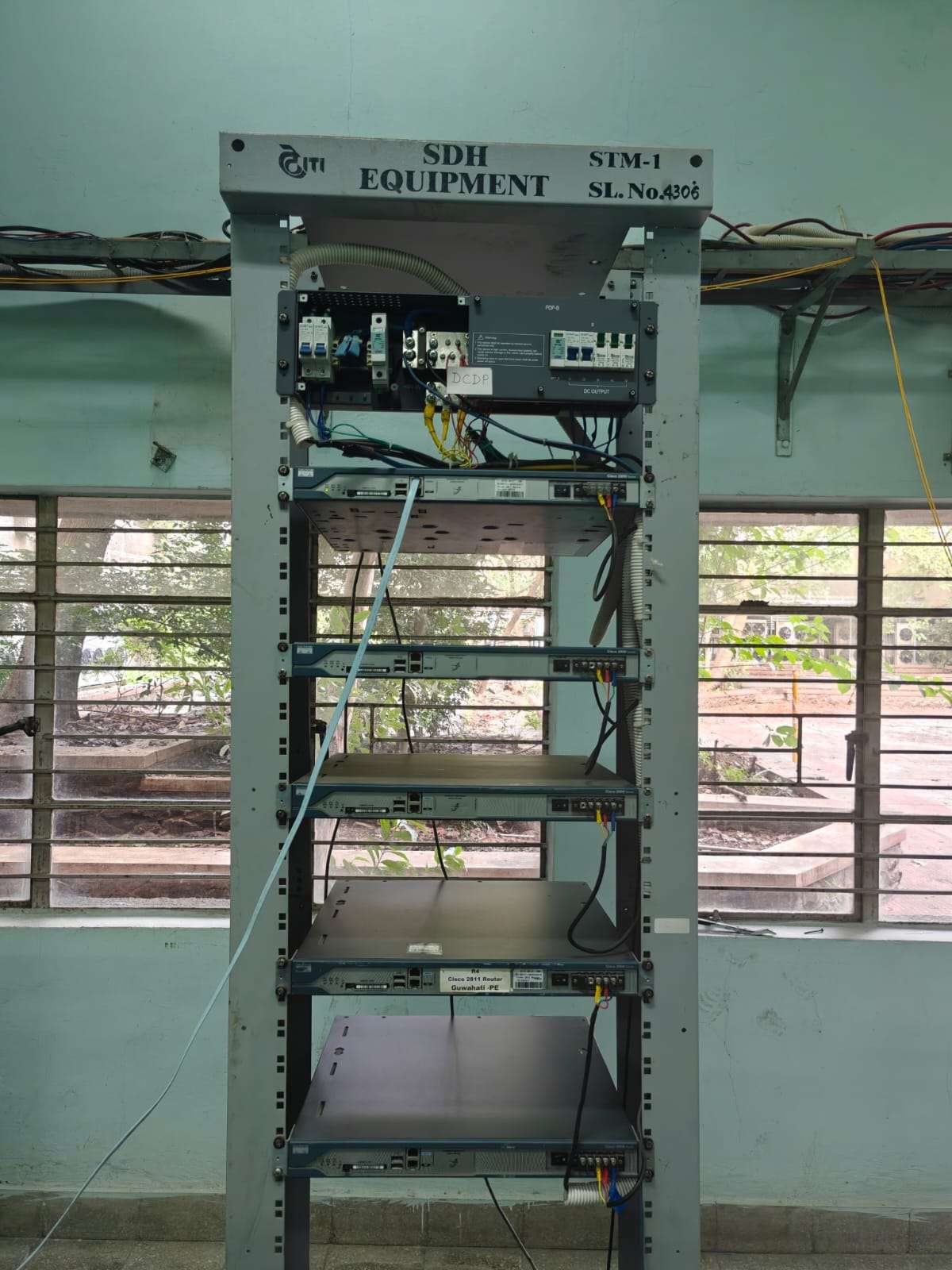
Step 5: Configured PE and CE Networks
The CE routers were connected to the PE routers. The required routing and MPLS VPN configurations were applied to provide communication between customer networks through the MPLS core. A typical MPLS L3VPN setup uses OSPF, LDP, VRFs, and BGP VPNv4.
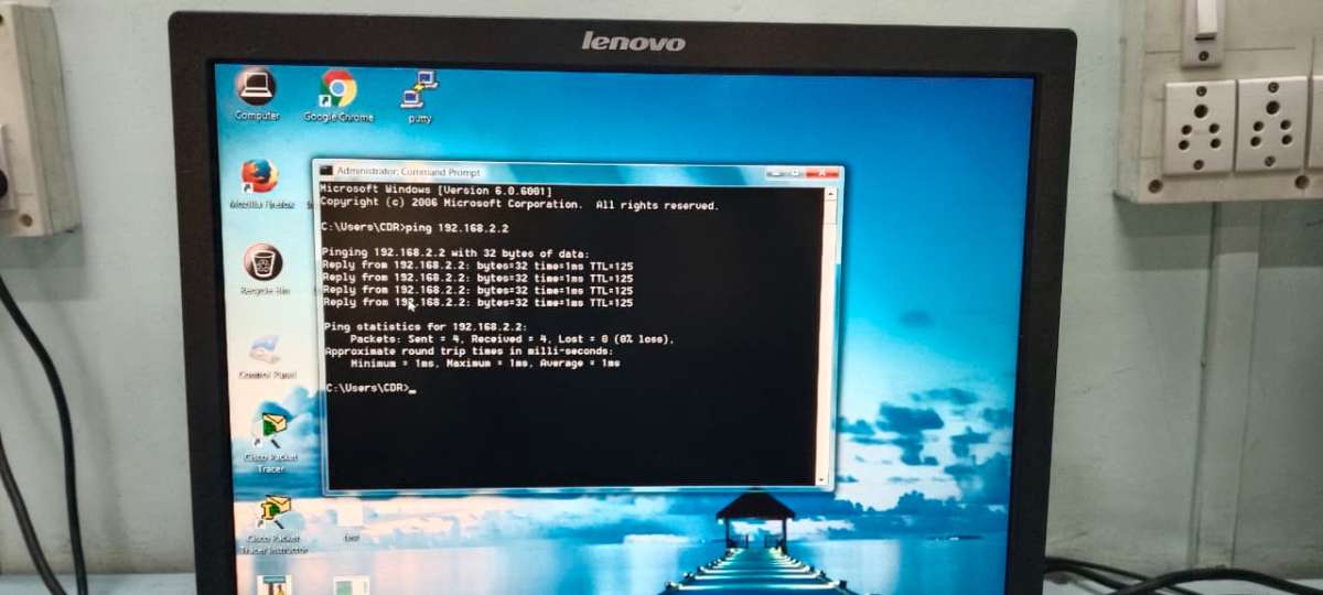
Step 6: Collected Network Performance Parameters
Network parameters such as latency, available bandwidth, and packet loss were considered to evaluate the condition of different paths.
Step7: AI-Based Path Selection
The AI-based decision mechanism analyzes the composite scores and identifies the most suitable path for traffic. This helps select a path based on current network conditions instead of relying only on a fixed routing decision.
Step 8: Tested the Network
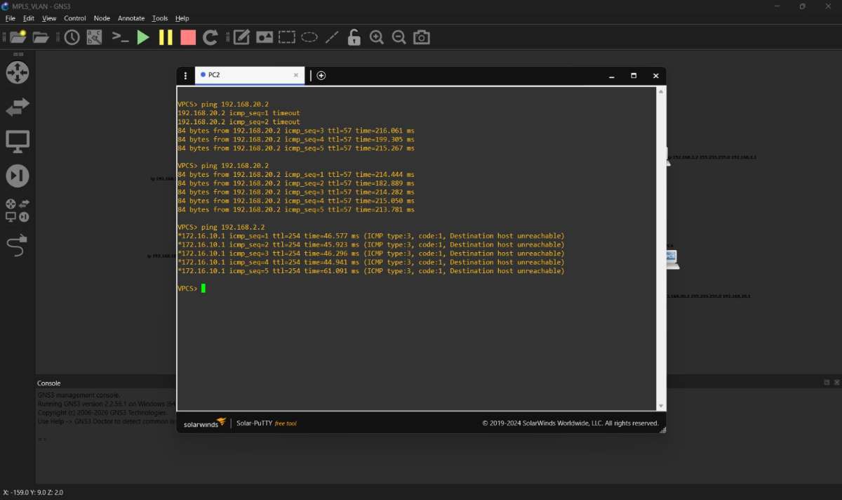
Different traffic conditions were tested in GNS3. Connectivity, routing, latency, packet loss, and path selection were monitored to evaluate the proposed optimization method.


