This project, attempts to control peripherals using UART commands with a Lolin D32 ESP32 board, leveraging the Arduino IDE for simplicity. This proof of concept demonstrates how to configure and control GPIO pins, PWM channels, and ADC readings through serial commands.
Materials Needed:
- Lolin D32 ESP32 board
- USB cable
- Computer with Arduino IDE installed
Step-by-Step Guide
1. Setting Up the Development Environment
First, you need to set up the Arduino IDE to work with the ESP32 board.
- Install Arduino IDE: Download and install the latest version of the Arduino IDE from the official website.
- Add ESP32 Board Support:
- Open Arduino IDE and navigate to File > Preferences.
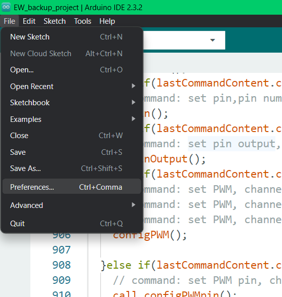
- Add the following URL to the Additional Boards Manager URLs: https://dl.espressif.com/dl/package_esp32_index.json.
- Open Arduino IDE and navigate to File > Preferences.
.png)
- Go to Tools > Board > Boards Manager, search for "ESP32", and install the package provided by Espressif Systems.
.png)
2. Connecting the Lolin D32 Board
- Connect the Board: Use a USB cable to connect the Lolin D32 to your computer.
- Select the Board and Port:
- In the Arduino IDE, go to Tools > Board and select "ESP32 Dev Module".
- Go to Tools > Port and select the port corresponding to the connected Lolin D32 board.
3. Code
Include libraries:
#include <string>
#include <Arduino.h>
Error messages: some functions may need the same error message, e.g., "message wrong length", so I decided to collect them all in the same array.
#define MAX_LENGTH 50 // Maximum length of the command string from user
#define maxNoOfCommandEntries 6 // Maximum number of sections a command has

// Error messages are stored in an array "errorMessag", these macros point to the error entries
#define unrecognisedcommand 0
#define messagewronglength 1
#define syntaxerror 2
#define invalidpinNo 3
#define miscelaniuserror 4
#define pinAlreadybeingused 5
#define iponly 6
#define doesNotExist 7
#define pinAlreadyUsed_pt1 8
#define pinAlreadyUsed_pt2 9

String errorMessag[] = {
    "\nunrecognised command\n", "\nmessage wrong length\n", "\ncommand has syntax error\n", "\ninvalid pin number\n",
    "\nerror ", "\nGPIO already being used, deactivate peripheral please, pin set to ", "\npin 34 is input only\n",
    " does not exist\n", "\npin already used as ", ", turn off peripheral or select other pin\n"
};
Define Pin Names and States: Create a struct to store pin states to manage the pin configurations ("pinState"). "pinName" will be used later.
// Struct to store the current function of a pin (input, output, PWM, etc.)
struct GPIOPinState {
    // Members (variables) of the struct
    String GPIO0;
    String GPIO2;

    String GPIO4;
    String GPIO5;

    String GPIO12;
    String GPIO13;

    String GPIO14;
    String GPIO15;
    String GPIO16;
    String GPIO17;
    String GPIO18;
    String GPIO19;

    String GPIO21;
    String GPIO22;
    String GPIO23;

    String GPIO25;
    String GPIO26;
    String GPIO27;

    String GPIO32;
    String GPIO33;
    String GPIO34;

  // Constructor to initialize the members, Ensures that when a struct of type "GPIOPinState" is created, its entries are initialized to "dig in "
  GPIOPinState() {
		GPIO0 = "dig in ";
		GPIO2 = "dig in ";
		GPIO4 = "dig in ";
		GPIO5 = "dig in ";
		GPIO12 = "dig in ";
		GPIO13 = "dig in ";
		GPIO14 = "dig in ";
		GPIO15 = "dig in ";
		GPIO16 = "dig in ";
		GPIO17 = "dig in ";
		GPIO18 = "dig in ";
		GPIO19 = "dig in ";
		GPIO21 = "dig in ";
		GPIO22 = "dig in ";
		GPIO23 = "dig in ";
		GPIO25 = "dig in ";
		GPIO26 = "dig in ";
		GPIO27 = "dig in ";
		GPIO32 = "dig in ";
		GPIO33 = "dig in ";
		GPIO34 = "dig in ";
	}
};


GPIOPinState pinState; // Struct to store the current function of a pin (input, output, PWM, etc.)
GPIOPinState pinName; // Struct used to save pin name (GPIO0, GPIO2, etc.)
Create pointers to struct elements: this array holds pointers to the elements of "GPIOPinState". This helps to access elements based on pin number. A lookup table will be used to attach pin number to array entry number, which in turn is used to access the struct elements (String GPIO0, String GPIO2, String GPIO4 ...).
// Pointers to different entries in the struct
String GPIOPinState::*members[] = {
  &GPIOPinState::GPIO0, &GPIOPinState::GPIO2,
  &GPIOPinState::GPIO4, &GPIOPinState::GPIO5,
  &GPIOPinState::GPIO12, &GPIOPinState::GPIO13, &GPIOPinState::GPIO14,
  &GPIOPinState::GPIO16, &GPIOPinState::GPIO17,
  &GPIOPinState::GPIO18, &GPIOPinState::GPIO19, &GPIOPinState::GPIO21,
  &GPIOPinState::GPIO22, &GPIOPinState::GPIO23, &GPIOPinState::GPIO25,
  &GPIOPinState::GPIO26, &GPIOPinState::GPIO27, &GPIOPinState::GPIO32,
  &GPIOPinState::GPIO33, &GPIOPinState::GPIO34
};
// Pointers to different entries in the struct in different order (used by the "printPins()" function)
String GPIOPinState::*orderAscii[] = {
	&GPIOPinState::GPIO23, &GPIOPinState::GPIO22, &GPIOPinState::GPIO34,
	&GPIOPinState::GPIO32, &GPIOPinState::GPIO21,
	&GPIOPinState::GPIO33, &GPIOPinState::GPIO19, &GPIOPinState::GPIO25,
	&GPIOPinState::GPIO18, &GPIOPinState::GPIO26, &GPIOPinState::GPIO5,
	&GPIOPinState::GPIO27, &GPIOPinState::GPIO17, &GPIOPinState::GPIO14,
	&GPIOPinState::GPIO16, &GPIOPinState::GPIO12, &GPIOPinState::GPIO4,
	&GPIOPinState::GPIO13, &GPIOPinState::GPIO0, &GPIOPinState::GPIO2,
	&GPIOPinState::GPIO15
};
Define LED PWM (LPWM) Details: another struct to store the LPWM details (what pins you attached to it, frequency, etc.). There are 16 channels (0-15), hence I used an array of structs "LPWM_state_struct LPWM_state" with an entry for every LPWM channel.
// Struct to store the settings of the 16 channels (0 to 15) of the LEDC (LED Control) PWM of the ESP32.
// This peripheral is used to generate a PWM signal using the LEDC functions of the ESP32
struct LPWM_state_struct{
  int on_off;
  int PWMresolution;
  int PWM_frequency;
  int dutyCycle;
  int max_dutyCycle;
  int PWM_pin[18]; // The PWM output can be on any of 18 pins, this array will hold the number of each pin connected to the PWM channel
  int number_of_pins; // The number of output pins connected to the PWM channel


  // Ensures that when a struct of type "LPWM_state_struct" is created, its values are initialized
  LPWM_state_struct(){
    on_off = 0;
    for(int i = 0; i < 18; i++){
      PWM_pin[i] = -1;
    }
    number_of_pins = 0;
  }

  // The maximum number that can be written to the duty cycle register depends on the resolution.
  // For example, for a duty cycle of 50%, a value = 0.5 * max_dutyCycle needs to be written. (the ledcWrite function will be used...)
  int get_max_dutyCycle(void){
    max_dutyCycle = 1 << PWMresolution;

    return(max_dutyCycle);
  }
};

LPWM_state_struct LPWM_state[16];// Array of structs of type "LPWM_state_struct" defined to store the settings of the 16 LEDC PWM channels
Check That Pin Number Is Valid For Board: make sure that the pin number sent in a command is available on the board.
// Function to make sure a pin number provided by the user is valid for the board
// This was made with the LOLIN D32 ESP32 board in mind
bool checkIfNoPinValid(int n){
  if (n < 0 || n == 1 || (n >= 6 && n <= 11) || n == 20 || n == 24 || (n >= 28 && n <= 31) || n > 34){
    return 0; // Pin does not exist or is already used by the board
  }
  return 1;
}
Check That Pin Number Is Valid For ADC1: make sure that the pin number sent in a command can be used as ADC1 output.
// check if pin can be used y ADC1
bool checkIfNoPinValid_ADC1(int n){
  if (n == 34 || n == 32 || n == 33){
    return 1; // Pin can be used by ADC1
  }
  return 0;
}
Remember the Look Up Table Mentioned earlier: it is used in this function to return the array entry number corresponding to the pin number from "*members".
// This function takes the pin number and returns the corresponding pointer in "orderAscii"
int pinNoToStructpointerIndx(int n){
  int mappingArray[] = {0,  2,  4,  5,  12,
  13, 14, 16, 17, 18,
  19, 21, 22, 23, 25,
  26, 27, 32, 33, 34};

  for(int i=0; i < 20; i++){
    if(n == mappingArray[i]){
      return i;
    }
  }
  Serial.println(errorMessag[miscelaniuserror] + "1\n");
  return -1;
}
Processing Commands: the user command is divided into the command name and the parameters:
// Example: user sends: "set PWM channel,0,10,1000,50,32"
//                       |_____________| |_____________|
//                              |               |
//                        command name  command parameters
Once a command is received, "processCommand()" will be called to run the necessary function (e.g., function to configure PWM, GPIO pins, etc.). The "processCommand()" function itself calls "parametriseString()" to separate the command into its parameters and store them in the struct "LASTCOMMANDCONTENT lastCommandContent".
// Struct to store the last command sent by the user through the serial monitor
struct LASTCOMMANDCONTENT{
  String commandName;
  String commandEntries[maxNoOfCommandEntries];
  int L_commandEntries;// number of command sections

  // Example: user sends "set PWM channel,0,10,1000,50,32"
  // commandName = "set PWM channel"
  // commandEntries = {"0", "10", "1000", "50", "32"}
  // L_commandEntries = 5
};
// take apart the user command string
LASTCOMMANDCONTENT lastCommandContent;
void parametriseString(String input){
// Example: user sends: "set PWM channel,0,10,1000,50,32"
// |_____________| |_____________|
// | |
// command name command parameters
// lastCommandContent.commandName = "set PWM channel"
// lastCommandContent.commandEntries[] = {"0", "10", "1000", "50", "32"}
// in this example 0 =channel, 10 =resolution, 10000 = frequency... the parameters are stored in an array
// lastCommandContent.L_commandEntries = 5
// Initialize struct members to 0
lastCommandContent.commandName = "\0";
for(int i = 0; i < maxNoOfCommandEntries; i++){
lastCommandContent.commandEntries[i] = "\0";
}
lastCommandContent.L_commandEntries = 0;
// Each part of the command sent by the user is separated by a ','
// The first part of the string is always the command name
int ip_indx = 0; // Index for user command (input)
// Go through the command string until you encounter a comma, or in the case of commands without "parameters", until the string ends
while(ip_indx < input.length() && input[ip_indx] != ','){
lastCommandContent.commandName += input[ip_indx];
ip_indx++;
}
ip_indx++;
int entry_indx = 0; // Index for the entry in the array "lastCommandContent.commandEntries"
// Go through the rest of the command string
for(ip_indx; ip_indx < input.length(); ip_indx++){
// If you don't encounter a ',' then add the character to "lastCommandContent.commandEntries"
if(input[ip_indx] != ','){
lastCommandContent.commandEntries[entry_indx] += input[ip_indx];
// if a ',' is encountered...
}else{
// ... increment the index "entry_indx"
entry_indx++;
// If the "entry_indx" exceeds the max number of entries in the array "lastCommandContent.commandEntries", break from the loop
if (entry_indx >= maxNoOfCommandEntries){
break;
}
}
// The command string ends with '\0', break before the end of command string is reached
if (input[ip_indx + 1] == '\0') {
entry_indx++; // Increment index, such that it is equal to the number of parameters sent in the user command
break;
}
}
lastCommandContent.L_commandEntries = entry_indx;
}void processCommand(const String& command){
parametriseString(command);
if(lastCommandContent.commandName == "print all"){
// command: print all
printPins();
prrintPWM();
}else if(lastCommandContent.commandName == "set pin"){
// command: set pin,pin number,i/p(1) or o/p(0)
setPin();
}else if(lastCommandContent.commandName == "set pin output"){
// command: set pin output, pin number, high or low
setPinOutput();
}else if(lastCommandContent.commandName == "set PWM channel"){
// command: set PWM, channel, resolution, frequencey,
// command: set PWM, channel, resolution, frequencey,duty cycle
// command: set PWM, channel, resolution, frequencey,duty cycle, pin
configPWM();
}else if(lastCommandContent.commandName == "set PWM pin"){
// command: set PWM pin, channel, pin
call_configPWMpin();
}else if(lastCommandContent.commandName == "set PWM duty cycle"){
// command: set PWM duty cycle, channel, duty cycle
change_PWM_duty();
}else if(lastCommandContent.commandName == "turn PWM off"){
// command: turn PWM off, channel
deactivate_PWM();
}else if(lastCommandContent.commandName == "adc1"){
// command: adc1, pin No,how many times to repeat reading
readADC();
}else{
Serial.println(errorMessag[unrecognisedcommand]);
}
}
Show Pin Function Using an ASCII diagram: the "printPins()" function is used to plot a diagram of the board showing the pin functions drawn on the serial monitor using ASCII art:
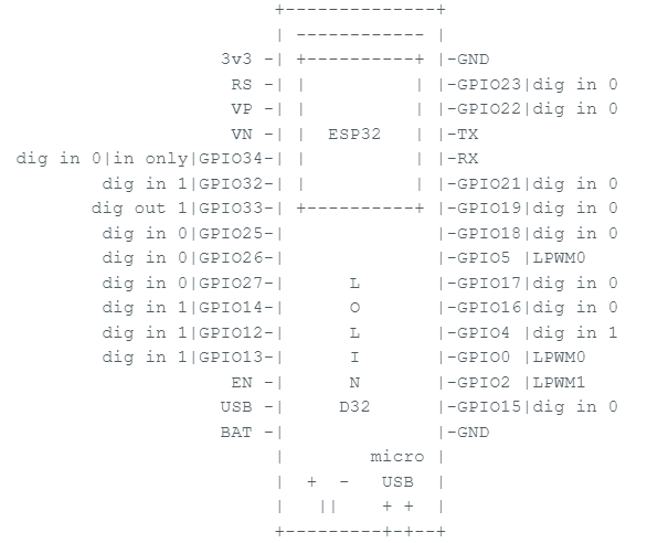
For digital inputs and outputs, the logic values are also shown:
// I used ASCII art of LOLIN ESP32 to show pins on the serial monitor
String ascii[]={"                           +--------------+\n                           | ------------ |\n                      3v3 -| +----------+ |-GND\n                       RS -| |          | |-GPIO23|",
            "                       VP -| |          | |-GPIO22|",
            "                       VN -| |  ESP32   | |-TX",
  "|in only|GPIO34-| |          | |-RX",
        "|GPIO32-| |          | |-GPIO21|",
        "|GPIO33-| +----------+ |-GPIO19|",
        "|GPIO25-|              |-GPIO18|",
        "|GPIO26-|              |-GPIO5 |",
        "|GPIO27-|      L       |-GPIO17|",
        "|GPIO14-|      O       |-GPIO16|",
        "|GPIO12-|      L       |-GPIO4 |",
        "|GPIO13-|      I       |-GPIO0 |",
        "                       EN -|      N       |-GPIO2 |",
        "                      USB -|     D32      |-GPIO15|",
        "                      BAT -|              |-GND\n                           |        micro |\n                           |  +  -   USB  |\n                           |   ||    + +  |\n                           +---------+-+--+\n"
};
// Function to print a diagram of the board on the serial monitor using ASCII art
void printPins(void){
// command: print all
int i, j, asciiIndx=0, No;
String ipOnly = "ip only|", space;
// The array "ascii" contains the board diagram in ASCII art.
// "asciiIndx" points to the specific entry in that array that should be printed.
// Print the first part of the ASCII art diagram
Serial.print(ascii[asciiIndx]);
asciiIndx++;
// Print pin descriptions using pointers stored in "orderAscii", which represent the correct order for the ASCII diagram.
// These pointers are passed to the function "printPinDescription()" (see its description).
Serial.println(printPinDescription( orderAscii[0] ));
// Print the next part of the ASCII art diagram
Serial.print(ascii[asciiIndx]);
asciiIndx++;
Serial.println(printPinDescription( orderAscii[1] ));
// Print the following ASCII art section
Serial.println(ascii[asciiIndx]);
asciiIndx++;
// When printing pin descriptions on the left of the serial monitor, it's crucial to use the correct number of spaces for alignment.
// Example:
// Without correct spacing:
// VN -| | ESP32 | |-TX
// dig ip 1|in only|GPIO34-| | | |-RX
// dig ip 1|GPIO32-| | | |-GPIO21|
//
// With correct spacing:
// VN -| | ESP32 | |-TX
// dig ip 1|in only|GPIO34-| | | |-RX
// dig ip 1|GPIO32-| | | |-GPIO21
// Ensure correct alignment when printing pin descriptions to the left of the serial monitor
if (pinState.*orderAscii[2] == "dig in " || pinState.*orderAscii[2] == "dig out "){
// for "dig in " and "dig out " I had to consider that one character representic the logc value will
No = findSpaceNo(pinState.*orderAscii[2], 10);
}else{
No = findSpaceNo(pinState.*orderAscii[2], 11);
}
//print spaces
for(j = 0; j<No; j++){
Serial.print(" ");
}
Serial.print(printPinDescription( orderAscii[2] ));
// Print the next ASCII art section
Serial.println(ascii[asciiIndx]);
asciiIndx++;
// Loop through and print remaining pin descriptions and ASCII art sections
for( i = 3; i < 18; i=i+2){
if (pinState.*orderAscii[i] == "dig in " || pinState.*orderAscii[i] == "dig out "){
No = findSpaceNo(pinState.*orderAscii[i], 18);
}else{
No = findSpaceNo(pinState.*orderAscii[i], 19);
}
// Print spaces
for(j = 0; j<No; j++){
Serial.print(" ");
}
Serial.print(printPinDescription( orderAscii[i] ));
// Print the next ASCII art section
Serial.print(ascii[asciiIndx]);
asciiIndx++;
Serial.println(printPinDescription( orderAscii[i+1] ));
}
Serial.println(ascii[asciiIndx] + printPinDescription( orderAscii[19] ));
asciiIndx++;
Serial.println(ascii[asciiIndx] + printPinDescription( orderAscii[20] ));
asciiIndx++;
Serial.println(ascii[asciiIndx]);
}// There is a function to print a diagram of the board on serial monitor using ASCII art, the "printPins()" function
// This also shows the pin's current function. For pins set as digital input or output, I also wanted them to show their logic value, in case of digital input or output
// Hence this function:
String printPinDescription(String GPIOPinState::*s /*input is pointer from the array "orderAscii"*/){
int pinIp;
// if pin is i/p or o/p, fined its logic value and return the pin state with the logic value...
if(pinState.*s == "dig in " || pinState.*s == "dig out "){
pinIp = digitalRead( findPinNo(s) );
return pinState.*s + String(pinIp);
}else{// ...else just return the pin state as described in the struct "pinState"
return pinState.*s;
}
}// Find the pin number based on the pointer
int findPinNo(String GPIOPinState::*s) {
String sh = pinName.*s; // The pinName struct has the same structure as pinState, but it contains the pin names such as GPIO0, GPIO2, and so on.
String No = sh.substring(4); // The 5th character corresponds to the pin number
// In case the pin number has 2 digits (e.g., "GPIO12"), the substring function reads from the 5th character onward to get the complete number.
// Remember, in C/C++, array indexing starts from 0.
return No.toInt(); // Convert to integer and return
}// Function to calculate the number of spaces needed for alignment
int findSpaceNo(String s, int L){
int sL = s.length();
return L - sL;
}
Print LPWM Channels status: remember the array "LPWM_state" stores the different channels' frequencies, duty cycles, pins, and resolution. This function displays these duties to the user on the serial monitor.
// Function to print details of the LPWM channels, which channels are active, frequency, output pins, etc
void prrintPWM(void){
  // command: print all

  // Loop through the array of structs "LPWM_state" which stores details of the LPWM channels...
  for(int i=0; i < 16; i++){
    Serial.print("channel " + String(i) + ":");
    if(LPWM_state[i].on_off == 0){
      Serial.println("off");
    }else{
      Serial.println("on");

      Serial.println("\tresolution " + String(LPWM_state[i].PWMresolution));
      Serial.println("\tfrequency " + String(LPWM_state[i].PWM_frequency));
      Serial.println("\tduty cycle " + String(LPWM_state[i].dutyCycle));
      Serial.println("\tmax duty cycle " + String(LPWM_state[i].max_dutyCycle));
      Serial.println("\toutput pins: ");

      // Loop through and print the pins associated with this channel
      for(int j = 0; j < LPWM_state[i].number_of_pins; j++){
        Serial.println("\t\tpin " + String(LPWM_state[i].PWM_pin[j]));
      }

    }
  }
}
The "printPins()" and "prrintPWM()" are called when the "print all" command is issued.
Configure Pin as Digital Input or Output: the "setPin()" function is called by the "set pin" command to change a GPIO pin to input or output (Command structure: set pin, pin number, i/p(1) or o/p(0)).
Note: if a pin is used by a peripheral you can't set it as anything else until the peripheral is switched off.
void setPin(void){
  // Command: set pin, pin number, i/p(1) or o/p(0)

  int pinNo;
  bool b0;
  int ip_or_op;
  bool b1;
  int p;
  String GPIO_state;

  // Check if the message is of correct length
  if(lastCommandContent.L_commandEntries == 2){

    // Convert command fields to numbers
    pinNo = lastCommandContent.commandEntries[0].toInt();
    b0 = (pinNo != 0 || lastCommandContent.commandEntries[0].equals("0"));

    ip_or_op = lastCommandContent.commandEntries[1].toInt();
    b1 = (ip_or_op != 0 || lastCommandContent.commandEntries[1].equals("0"));
  }else{
    Serial.println(errorMessag[messagewronglength]);
    return;
  }

  // Check if both b0 and b1 are true, indicating both parameters were numbers
  if (!(b0 && b1)){
    Serial.println(errorMessag[syntaxerror]);
    return;
  }else if (!(checkIfNoPinValid(pinNo))){ // Check if pin number is valid
    Serial.println(errorMessag[invalidpinNo]);
    return;
  }

  p = pinNoToStructpointerIndx(pinNo);
  if (p < 0){ // "pinNoToStructpointerIndx()" returns -1 for invalid number
    return;
  }else{
    // make sure GPIO pin is set as an i/p or o/p and is not used by a peripheral by checking it's entry in the "pinState" struct
    GPIO_state = pinState.*members[p];
    if( GPIO_state == "dig in " || GPIO_state == "dig out " ){
      // Check if the user wants to set the pin as input or output
        if(ip_or_op == 0){
          if (pinNo == 34){  // Input pins only
            Serial.println(errorMessag[iponly]);
          }else{
            pinMode(pinNo, OUTPUT);
            pinState.*members[p] = "dig out ";
          }
        }else{
          pinMode(pinNo, INPUT);
          pinState.*members[p] = "dig in ";
        }
    }else{
      Serial.println(errorMessag[pinAlreadybeingused] + GPIO_state + "\n");
      return;
    }
  }

}
Set Output Pin Logic Level: the command "set pin output" calls the "setPinOutput()" to set output pin logic level (command structure: set pin output, pin number, high or low):
// set output pin high or low
void setPinOutput(void){
  // command: set pin output, pin number, high or low

  int PWM_pin;
  unsigned int H_L;
  bool b0, b1;

  // Check if the message is of correct length
  if(!(lastCommandContent.L_commandEntries == 2)){
    Serial.println(errorMessag[messagewronglength]);
  }else{

    // Convert command fields to numbers
    PWM_pin = lastCommandContent.commandEntries[0].toInt();
    b0 = (PWM_pin != 0 || lastCommandContent.commandEntries[0].equals("0"));

    H_L = lastCommandContent.commandEntries[1].toInt();
    b1 = (H_L != 0 || lastCommandContent.commandEntries[1].equals("0")) && H_L < 2;

    int m = pinNoToStructpointerIndx(PWM_pin);

     // Check if both b0 and b1 are true, indicating both parameters were numbers
    if (!(b0 && b1)){
      Serial.println(errorMessag[syntaxerror]);
    }else  if (!(checkIfNoPinValid(PWM_pin))){// Check if pin number is valid
      Serial.println(errorMessag[invalidpinNo]);
    }else  if (PWM_pin == 34){// Ensure pin isn't input only
      Serial.println(errorMessag[iponly]);
    }else if (pinState.*members[m] != "dig out "){// Ensure pin is set as output
      Serial.println("\npin not set as output pin\n");
    }else{
      digitalWrite(PWM_pin, H_L); // Set output logic level
    }

  }
  return;
}
"configPWMpin()" Function: called when code needs to attach a pin to LPWM channel.
// other functions will call this set a pin as a LPWM channel o/p
void configPWMpin(int PWMchannel, int PWM_pin){

  // Check if the pin is valid
  if (checkIfNoPinValid(PWM_pin) && PWM_pin != 34){
    int m = pinNoToStructpointerIndx(PWM_pin);

    // Make sure that the pin isn't already used by a peripheral
    if(pinState.*members[m] == "dig in " || pinState.*members[m] == "dig out "){

      // Attach pin to PWM channel
      ledcAttachPin(PWM_pin, PWMchannel);

      // Update pin state struct "pinState"
      pinState.*members[m] = "LPWM" + String(PWMchannel);

      // Update "LPWM_state" struct as well
      LPWM_state[PWMchannel].PWM_pin[LPWM_state[PWMchannel].number_of_pins] = PWM_pin;
      LPWM_state[PWMchannel].number_of_pins++;

    }else{
      Serial.println(errorMessag[pinAlreadyUsed_pt1] + pinState.*members[m] + errorMessag[pinAlreadyUsed_pt2]);
    }
  }else{
    Serial.println(errorMessag[invalidpinNo]);
    return;
  }
}
Start a PWM channel: the "configPWM()" function is used to start one of the LPWM channels. To start the LPWM, the channel number, frequency, and resolution are needed. The function can also take the duty cycle and pin number as inputs:
command structure: set PWM, channel, resolution, frequency
or: set PWM, channel, resolution, frequency, duty cycle
or: set PWM, channel, resolution, frequency, duty cycle, pin
Remember, LED PWM (LPWM) has 16 channels (0-15), and a maximum frequency dependent on the resolution, max frequency = 80MHz / (2^PWMresolution). By default, LPWM channels use an 80MHz clock.
About the range of the resolution, from analyzing the library code I think the resolution can actually reach 20. However, the documentation of the LED Control library (https://docs.espressif.com/projects/esp-idf/en/latest/esp32/apireference/peripherals/ledc.html?highlight=pwm#ledc-api-configure-timer) seems to indicate a range of 0 to 15. To be sure, the code only allows the user a duty cycle > 0 and < 15.
// This is called to start the LPWM
void configPWM(void){
    // command: set PWM, channel, resolution, frequencey
    // or:      set PWM, channel, resolution, frequencey,duty cycle
    // or:      set PWM, channel, resolution, frequencey,duty cycle, pin
    bool b0, b1, b2, b3, b4;
    int PWMchannel, PWMresolution, PWM_frequency, dutyCycle, PWM_pin;
    int max_frequency = 0;

    // Check that message is correct length
    if(lastCommandContent.L_commandEntries >= 3 && lastCommandContent.L_commandEntries <= 5){

      // Convert command fields to numbers
      PWMchannel = lastCommandContent.commandEntries[0].toInt();
      b0 = (PWMchannel != 0 || lastCommandContent.commandEntries[0].equals("0"));

      PWMresolution = lastCommandContent.commandEntries[1].toInt();
      b1 = (PWMresolution != 0 || lastCommandContent.commandEntries[1].equals("0"));

      PWM_frequency = lastCommandContent.commandEntries[2].toInt();
      b2 = (PWM_frequency != 0 || lastCommandContent.commandEntries[2].equals("0"));

      // Since this command can have different lengths:
      if(lastCommandContent.L_commandEntries > 3){ // If the command has more than 3 parameters, the duty cycle was sent
        dutyCycle = lastCommandContent.commandEntries[3].toInt();
        b3 = (dutyCycle != 0 || lastCommandContent.commandEntries[3].equals("0"));

        if(lastCommandContent.L_commandEntries > 4){ // If the command has more than 4 parameters, a pin number to set as channel output was sent
          PWM_pin = lastCommandContent.commandEntries[4].toInt();
          b4 = (PWM_pin != 0 || lastCommandContent.commandEntries[4].equals("0"));
        }else{ // Set "PWM_pin" to -1 to show that the user hasn't sent a pin number
          PWM_pin = -1;
          b4 = 1;
        }
      }else{ // If the command only had 3 fields, then the user hasn't set a pin number to attach to channel or duty cycle
        // Default duty cycle
        dutyCycle = 50;
        b3 = 1;

        // Set "PWM_pin" to -1 to show that the user hasn't sent a pin number
        PWM_pin = -1;
        b4 = 1;
      }

       // Check that both b0, b1, b2, b3, and b4 are logic true, implies parameters where all are numbers
      if(b0 && b1 && b2 && b3 && b4){

        // ESP32 has LPWM 16 channels (0 to 15)
        if( PWMchannel >= 0 || PWMchannel <16){

          // I think the resolution can actually reach 2^20 when I looked at the function definition, however the documentation of the LED Control library:
          // https://docs.espressif.com/projects/esp-idf/en/latest/esp32/api-reference/peripherals/ledc.html?highlight=pwm#ledc-api-configure-timer
          // seem to indicate a range of 0 to 15...
          if( PWMresolution > 0 || PWMresolution <15){

            // I think clk frequency for PWM is 80MHz by default, not 100% sure
          max_frequency = 80000000 / (1 << PWMresolution); // The max output frequency of the PWM depends on the resolution
            if (PWM_frequency <= max_frequency){
              bool rledcSetp;

              // Set up PWM channel, frequency, and resolution using the library function... it returns false if setup failed
              rledcSetp = ledcSetup(PWMchannel, PWM_frequency, PWMresolution);

              if (rledcSetp){ // If setup succeeded
                LPWM_state[PWMchannel].PWM_frequency = PWM_frequency;
                LPWM_state[PWMchannel].PWMresolution = PWMresolution;
                LPWM_state[PWMchannel].on_off = 1;

                // "duty_cycle_limith" is the max number that can be written to the duty cycle register, writing 0.5*duty_cycle_limith => duty cycle of 50%...
                int duty_cycle_limith = LPWM_state[PWMchannel].get_max_dutyCycle();// Refer to "LPWM_state_struct"

                // Make sure that the user provided a duty cycle in the range of 0 to 100%
                if(dutyCycle > 0 && dutyCycle < 100){
                  dutyCycle = (int)(dutyCycle*LPWM_state[PWMchannel].max_dutyCycle)/100;

                  ledcWrite(PWMchannel, dutyCycle);
                  LPWM_state[PWMchannel].dutyCycle = dutyCycle;// Update "LPWM_state"

                  if (PWM_pin != -1){// // Remember, the variale "PWM_pin" is set to -1 if the user didn't provide a pin number
                    configPWMpin(PWMchannel, PWM_pin);
                  }
                }else{
                  Serial.println("\nDuty Cycle should be from 0 to 100\n");
                }
              }else{
                Serial.println("\nledc setup failed\n");
              }

            }else{
              Serial.println("\nFrequency too high");
              Serial.println("At this resolution, max frequency is:" + String(max_frequency) + "\n");
            }

          }else{
            Serial.println("\nInvalid resolution");
            Serial.println("Valid resolutions: 1 to 14\n");
          }
        }else{
          Serial.print("\nPWM channel " + String(PWMchannel) + errorMessag[doesNotExist]);
          Serial.println("Valid channel numbers: 0 to 15\n");
        }

      }else{
        Serial.println(errorMessag[syntaxerror]);
      }
    }else{
      Serial.println(errorMessag[messagewronglength]);
    }
    return;

}
Attaching pin to channel: the "call_configPWMpin()" is called by the command "set PWM pin" to attach an output pin to a channel (command structure: set PWM pin, channel, pin number). Channels can have multiple outputs.
// Called when user wants to attach a pin to a LPWM channel
void call_configPWMpin(void){
  // command: set PWM pin, channel, pin number
  bool b0, b1;
  int PWMchannel, PWM_pin;

  // Check that message is correct length
  if(lastCommandContent.L_commandEntries == 2){

    // Convert command fields to numbers
    PWMchannel = lastCommandContent.commandEntries[0].toInt();
    b0 = (PWMchannel != 0 || lastCommandContent.commandEntries[0].equals("0"));
    PWM_pin = lastCommandContent.commandEntries[1].toInt();
    b1 = (PWM_pin != 0 || lastCommandContent.commandEntries[1].equals("0"));

    // Check that both b0 and b1 are logic true, implies parameters where both are numbers
    if(b1 && b0){
      // Call "configPWMpin()" to set
      configPWMpin(PWMchannel, PWM_pin);
    }else{
      Serial.println(errorMessag[syntaxerror]);
    }
  }else{
    Serial.println(errorMessag[messagewronglength]);
  }

  return;
}
Change channel duty cycle: the "change_PWM_duty()" is called by the command "set PWM duty cycle" to adjust an LPWM channel's duty cycle (command structure: set PWM duty cycle, channel, duty cycle). Note, the duty cycle is given as a percentage without the "%" sign, for example: "set PWM duty cycle,0,50".
void change_PWM_duty(void){
  // Command: set PWM duty cycle, channel, duty cycle
  // The ESP32 has 16 channels (0-15)
  // Duty cycle ranges from 0 - 100 percent (do not include % sign when sending command string)
  // ex: set PWM duty cycle,0,50

  bool b0, b1, b2, b3, b4;
  int PWMchannel, dutyCycle;

  // Check if the correct number of parameters was received
  if (lastCommandContent.L_commandEntries == 2) {

    // Convert the first parameter from string format to number (see "parametriseString()")
    PWMchannel = lastCommandContent.commandEntries[0].toInt();
    b0 = (PWMchannel != 0 || lastCommandContent.commandEntries[0].equals("0"));
    // Convert the second parameter from string format to number
    dutyCycle = lastCommandContent.commandEntries[1].toInt();
    b1 = (dutyCycle != 0 || lastCommandContent.commandEntries[1].equals("0"));

    // Note: The "toInt()" function returns 0 if an error occurred. For example, if "lastCommandContent.commandEntries[0]"" was not a number, it will return 0.
    // To check if that happened:
    //                                     (PWMchannel != 0 || lastCommandContent.commandEntries[0].equals("0"));
    //                                      |______________|   |_______________________________________________|
    //                                             |                                    |
    //  if function didn't return a 0, then no error occurred       if it returned a 0, then string must be = "0"

    // Check if both b0 and b1 are true, indicating both parameters were numbers
    if(b0 && b1){
      // make sure that the PWM channel chosen is on. Remember LPWM_state is an array of structs holding the details of the LPWM  channels...
      // ... each entry corresponds to a channel
      if (LPWM_state[PWMchannel].on_off == 1){

        // make sure that the duty cyle isn't > 100% or <0%
        if(dutyCycle > 0 && dutyCycle < 100){
          dutyCycle = (int)(dutyCycle*LPWM_state[PWMchannel].max_dutyCycle)/100;
          // The "max_dutyCycle" depends on the PWM resolution (see "LPWM_state_struct")

          ledcWrite(PWMchannel, dutyCycle);// right new PWM duty cycle
          LPWM_state[PWMchannel].dutyCycle = dutyCycle;// update the struct "LPWM_state"
        }else{
          Serial.println("\nDuty Cycle should be from 0 to 2^resolution = " + String(LPWM_state[PWMchannel].max_dutyCycle) + "\n");
        }
      }else{
        Serial.println("\nthis channel is off\n");
      }
    }else{
      Serial.println(errorMessag[syntaxerror]);
    }

  }else{
    Serial.println(errorMessag[messagewronglength]);
  }
  return;

}
Turn off channel when no longer needed: to deactivate a channel, use the "turn PWM off" command (command structure: turn PWM off, channel). The deactivated channel's output pins will be reset as digital inputs so that they can be used for other peripherals.
// Called when you want to turn LPWM channel off
void deactivate_PWM(void){
  // command: turn PWM off, channel

  int PWMchannel;
  bool b0;

  // Check that message is correct length
  if(lastCommandContent.L_commandEntries == 1){

    // Convert command fields to numbers
    PWMchannel = lastCommandContent.commandEntries[0].toInt();
    b0 = (PWMchannel != 0 || lastCommandContent.commandEntries[0].equals("0"));

    // Check that b0 is logic true, implies parameter is a number
    if (b0) {
      // ESP32 has 16 channels (0 to 15)
      if( PWMchannel >= 0 || PWMchannel <16){

        ledcWrite(PWMchannel, 0); // Set duty cycle to 0 to deactivate PWM

         // Reset the entry in the struct array "LPWM_state" corresponding to the channel to default value
        for(int i = 0; i < LPWM_state[PWMchannel].number_of_pins; i++){
          if(LPWM_state[PWMchannel].PWM_pin[i] != -1){
            int pinNo = LPWM_state[PWMchannel].PWM_pin[i];
            int p = pinNoToStructpointerIndx(pinNo);
            ledcDetachPin(pinNo);
            pinMode(pinNo, INPUT);
            pinState.*members[p] = "dig in ";

            LPWM_state[PWMchannel].PWM_pin[i] = -1;
          }
        }
        LPWM_state[PWMchannel].number_of_pins = 0;
        LPWM_state[PWMchannel].on_off = 0;

      }else{
        Serial.print("\nPWM channel " + String(PWMchannel) + errorMessag[doesNotExist]);
      }
    }else{
      Serial.println(errorMessag[syntaxerror]);
    }

  }else{
    Serial.println(errorMessag[messagewronglength]);
  }

  return;
}
Reading analog input: the "readADC()" function is used to take a number of analog readings using ADC1, then resetting the analog pin used to its original function (digital input or output). If this project wasn't a proof of concept with more projects lined up, it would have worked more like the PWM functions where the ADC pin is stored in a struct and another function has to be called to deactivate it.
(command structure: adc1, pin No, how many times to repeat reading)
// Used to take a number of analog readings using ADC1
void readADC(void){
  //command: adc1, pin No,how many times to repeat reading

  int digitalValue = 0;  // Variable to store the value coming from the sensor
  float analogVoltage = 0.00;

  bool b0, b1;
  int ADC_pin, No_of_repeats;

  // Check that message is correct length
  if(lastCommandContent.L_commandEntries == 2){

    // Convert command fields to numbers
    ADC_pin = lastCommandContent.commandEntries[0].toInt();
    b0 = (ADC_pin != 0 || lastCommandContent.commandEntries[0].equals("0"));

    No_of_repeats = lastCommandContent.commandEntries[1].toInt();
    b1 = (No_of_repeats != 0 || lastCommandContent.commandEntries[1].equals("0"));

    // Check that both b0 and b1 are logic true, implies parameters where both are numbers
    if(b0 && b1){

      // Call "checkIfNoPinValid_ADC1()" to make sure the pin number sent by the user is valid
      if (checkIfNoPinValid_ADC1(ADC_pin)){
        int   p = pinNoToStructpointerIndx(ADC_pin);

        // Make sure pin isn't already used by another peripheral
        if(pinState.*members[p] == "dig in " || pinState.*members[p] == "dig out "){

          // Take a number of readings based on the user input every 500ms
          for(int i=1; i <= No_of_repeats;i++){
            digitalValue = analogRead(ADC_pin);// Read the value from the analog channel
            // The ADC returns a digital value between 0 (0V) to 4095 (3.3V)
            analogVoltage = (digitalValue * 3.3)/4095.00; // Convert from digital reading to analog value
            Serial.print("  Analog voltage = ");
            Serial.println(analogVoltage);

            if(No_of_repeats != i){
              delay(500);
            }
          }

          // Return the pin to its original function
          if(pinState.*members[p] == "dig in " ){
            pinMode(ADC_pin, INPUT);
          }else{
            pinMode(ADC_pin, OUTPUT);
          }


        }else{
          Serial.println(errorMessag[pinAlreadyUsed_pt1] + pinState.*members[p] + errorMessag[pinAlreadyUsed_pt2]);
        }

      }else{
        Serial.println(errorMessag[invalidpinNo]);
      }
    }else{
      Serial.println(errorMessag[syntaxerror]);
    }
  }else{
    Serial.println(errorMessag[messagewronglength]);
  }

}
Setup: at the start of the code, the serial monitor is started and set to a baud rate of 115200 bps. The entries of the struct "pinName" are initialized. By default, pins are set to digital inputs. However, to ensure correctness, "setup()" configures them explicitly as digital inputs.
void setup() {
  Serial.begin(115200); // Start serial monitor

  // Initialise "pinName" struct
  pinName.GPIO0 = "GPIO0";

	pinName.GPIO2 = "GPIO2";

	pinName.GPIO4 = "GPIO4";
	pinName.GPIO5 = "GPIO5";

  pinName.GPIO12 = "GPIO12";
	pinName.GPIO13 = "GPIO13";
	pinName.GPIO14 = "GPIO14";
	pinName.GPIO14 = "GPIO15";

	pinName.GPIO16 = "GPIO16";
	pinName.GPIO17 = "GPIO17";
	pinName.GPIO18 = "GPIO18";
	pinName.GPIO19 = "GPIO19";

  pinName.GPIO21 = "GPIO21";
	pinName.GPIO22 = "GPIO22";
	pinName.GPIO23 = "GPIO23";
	pinName.GPIO25 = "GPIO25";
	pinName.GPIO26 = "GPIO26";
	pinName.GPIO27 = "GPIO27";

  pinName.GPIO32 = "GPIO32";
	pinName.GPIO33 = "GPIO33";
	pinName.GPIO34 = "GPIO34";

  // Make sure all pins are inputs
  int listOfPins[] ={34, 32, 33,25,26,27,14,12,13,23,22,21,19,18,5,17,16,4,0,2,15} ;
  for(int i = 0; i < 21; i++){
    pinMode(listOfPins[i], INPUT);
  }

  // Print ASCII diagram of board
  printPins();
}
Loop: the "loop()" function polls the serial monitor waiting for user input. The user input must end with a terminator '\n' or '\r'. After the command string is received, the terminator is replaced by the null-terminator '\0', and "processCommand()" is called.
void loop() {
  if (Serial.available() > 0) {
    char receivedString[MAX_LENGTH + 1]; // Buffer to store the received string
    memset(receivedString, 0, sizeof(receivedString)); // Clear the buffer

    int index = 0;
    while (Serial.available() > 0 && index < MAX_LENGTH) {
        char incomingChar = Serial.read(); // Read the incoming character
        receivedString[index] = incomingChar; // Store the character in the buffer
        index++;

        // Check for termination character (newline '\n' or carriage return '\r')
        if (incomingChar == '\n' || incomingChar == '\r') {
            break; // Exit the loop if termination character is received
        }
    }

    // Null-terminate the string
    receivedString[index] = '\0';
    if (receivedString[index - 1] == '\n' || receivedString[index-1] == '\r') {
      receivedString[index - 1] = '\0';
    }

    String receivedStringObject(receivedString);

    // Call "processCommand()" if a command is received
    processCommand(receivedStringObject);
  }
}
4. Uploading the Code
- Upload Code
- Monitor Serial Output:
- Open the Serial Monitor in Arduino IDE to see the output and interact with the board (set it to new lline).
.png)
5. Using the Lolin D32 Board with Arduino IDE
- Send Commands via Serial Monitor:
- Use the Serial Monitor to send commands to the Lolin D32 board. For example:
- "set pin,13,1" to set GPIO13 as an output pin.
- "set pin output,13,1" to set GPIO13 to high.
- "set PWM,0,8,5000,50" to configure PWM channel 0 with 8-bit resolution, 5000 Hz frequency, and 50% duty cycle.
- "adc1,34,10" to read ADC value from pin GPIO34, 10 times.
- Use the Serial Monitor to send commands to the Lolin D32 board. For example:
- Verify Responses:
- Check the Serial Monitor for responses from the board indicating the success or failure of the commands.