
USB-C PD chargers are everywhere these days. Most of us already have a 30W, 65W, or even 100W charger sitting in a drawer. While they're usually used for charging phones and laptops, they can also be used as surprisingly capable power sources.
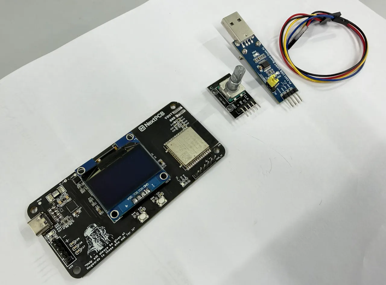
That inspired me to build PowerPD, a compact ESP32-based programmable power supply that turns a USB-C PD charger into a small bench supply. Using an AP33772S PD controller, it can negotiate different voltage profiles from a compatible charger, while an INA226 monitors voltage, current, and power in real time.
Using the rotary encoder, I can select standard PD voltages such as 5V, 9V, 12V, 15V, and 20V. If the charger supports PPS, the output voltage can also be adjusted in smaller steps. The OLED display shows live measurements, and the ESP32 can even send data to Adafruit IO for remote monitoring.
Main Components
- ESP32-WROOM-32E Module
- AP33772S USB-C PD Sink Controller
- INA226 Voltage/Current Monitor
- MP1584 Buck Converter
- AP2204K 3.3V Regulator
- USB Type-C Connector
- 5 mΩ Current Sense Resistor
- MOSFET Output Switch
- 1.3-inch SH1106 OLED Display
- Rotary Encoder
- Push Buttons
- Status LEDs
- Assorted resistors, capacitors, diodes, and other passive components
Tools
- USB-C PD Charger (supports at least 9V PD)
- 3.3V USB-to-UART Adapter (CP2102, CH340, or FT232RL)
- Jumper Wires
- Multimeter
Step 1: Working Principle

Before getting into the hardware, it helps to understand how PowerPD works.
When a USB-C PD charger is connected, it starts at the default 5V output. The AP33772S then reads the voltage profiles supported by the charger and negotiates the requested PD or PPS voltage.

Once the voltage is selected, power flows through the 5 mΩ shunt resistor and MOSFET output switch before reaching the output terminals. The INA226 continuously measures voltage, current, and power, then sends the data to the ESP32 over I²C.
The ESP32 updates the OLED display, handles the rotary encoder and buttons, controls the output switch, and can optionally send live data to Adafruit IO over Wi-Fi.
The onboard buck converter and 3.3V regulator power the ESP32 and other logic circuits directly from the USB-C input.
Step 2: Circuit Overview

The USB-C connector provides both power and communication with the PD charger. The AP33772S handles PD negotiation and requests the selected voltage profile, such as 5V, 9V, 12V, 15V, or 20V.

Voltage and Current Monitoring
A 5 mΩ shunt resistor and INA226 monitor the output voltage, current, and power in real time. This data is sent to the ESP32 over I²C.
Output Switching
A MOSFET acts as an electronic power switch, allowing the ESP32 to safely enable or disable the output.
Internal Power Supply
The MP1584 buck converter reduces the input voltage, while the AP2204K regulator generates a stable 3.3V supply for the ESP32 and other logic circuits.

ESP32 Controller
The ESP32 manages the entire system. It handles PD negotiation, reads measurement data, updates the OLED display, processes user inputs, and can optionally send data to Adafruit IO over Wi-Fi.
User Interface
The board uses a 1.3-inch SH1106 OLED display, a rotary encoder, and push buttons for voltage selection, menu navigation, and output control.
USB-C PD, PPS, and AVS Basics
USB-C PD chargers can provide multiple voltage levels depending on their capabilities. The most common PD profiles are:
- 5V
- 9V
- 12V
- 15V
- 20V
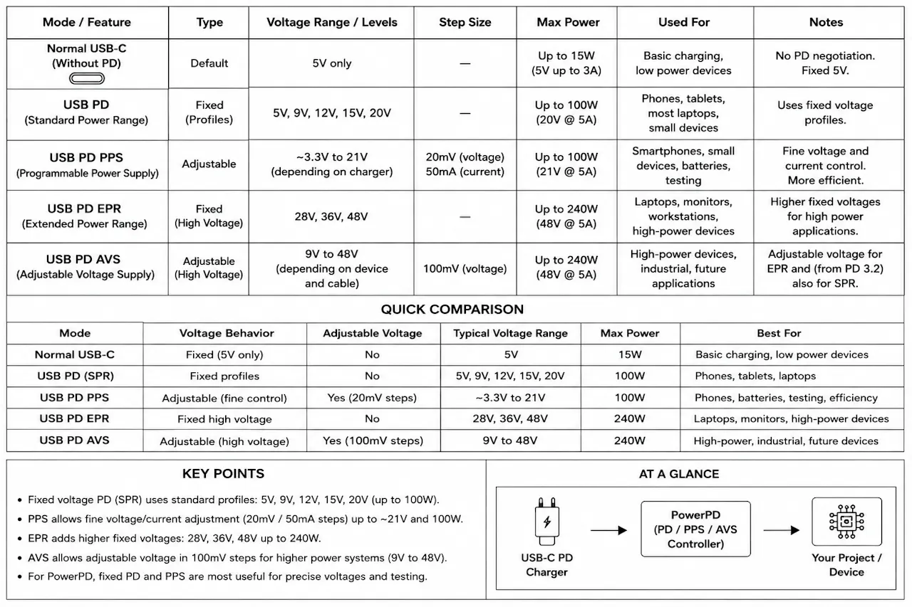
These fixed voltage levels work well for most applications, but sometimes a project needs a voltage in between. That's where PPS comes in.
PPS (Programmable Power Supply)
PPS allows the charger to adjust its output voltage in small steps instead of switching only between fixed profiles. This makes it useful for powering prototypes, testing circuits, and other electronics projects that require more flexibility.
Not all USB-C PD chargers support PPS, so it's worth checking the charger specifications before using this feature.
EPR (Extended Power Range)
Newer USB-C chargers may support EPR, which adds higher voltage levels such as 28V, 36V, and 48V for high-power devices.
PowerPD currently supports standard PD and PPS profiles only.
AVS (Adjustable Voltage Supply)
AVS is another adjustable voltage feature introduced in newer USB PD specifications. It is designed for higher-power applications and is not currently supported by PowerPD.
Before requesting any voltage, always check what your charger supports. The AP33772S can only negotiate profiles advertised by the charger.

PCB Design and Assembly

My friend Rabindra designed the PowerPD PCB in EasyEDA. He also handled the design research, component selection, schematic planning, PCB layout, and overall development process.

The AP33772S is placed close to the USB-C connector to keep the CC traces short, while the INA226 sits next to the 5 mΩ shunt resistor for accurate current sensing.
Since several components use fine-pitch packages, including the AP33772S and USB-C connector, I decided to have the boards professionally assembled. For this project, I used NextPCB for both fabrication and assembly.

After uploading the Gerber files, BOM, and pick-and-place file, NextPCB handled component sourcing and assembly. Before shipping, they sent photos of the completed boards so I could verify the component placement.
Firmware Overview
To communicate with the AP33772S USB-C PD controller, I created a custom Arduino library for this project. The library, firmware, and project files are available on GitHub.
To compile the project, place the following files in the same Arduino sketch folder:
- PowerPD.ino
- AP33772S.h
- AP33772S.cpp
Before uploading the firmware, install these libraries:
- U8g2
- INA226
- PubSubClient
The ESP32 handles PD/PPS negotiation, reads measurements from the INA226, updates the OLED display, processes user inputs, controls the output MOSFET, and can optionally send data to Adafruit IO over Wi-Fi.
On startup, the ESP32 checks the AP33772S and INA226, reads the available PD profiles from the charger, and displays the main interface. From there, the user can select a voltage, enable the output, and monitor live measurements.
Step 6: Adafruit IO Setup
PowerPD can also send live data to Adafruit IO, so I can monitor the board from a web dashboard. For this project, I kept the dashboard simple and only used the values that really matter:
- voltage
- current
- power
- temperature
- output
This is enough to see the real-time condition of the power supply without filling the dashboard with unnecessary data.
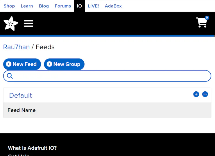
1. Open Adafruit IO
First, go to Adafruit IO and log in to your account.
https://io.adafruit.com/After login, you will see the Adafruit IO overview page. Since I am using the Basic plan, I can create up to 10 feeds, which is enough for this project.

2. Create the Feeds
Go to:
Feeds → New Feed
Create these five feeds one by one:
- voltage
- current
- power
- temperature
- output
I used short feed names because these same names are used in the ESP32 code.
For the descriptions, I used simple text like this:
- voltage Live output voltage measured by PowerPD
- current Live load current measured by PowerPD
- power Real-time output power
- temperature Board / PD controller temperature
- output Output state, 0 = OFF and 1 = ON

3. Create a Dashboard
After creating the feeds, go to:
- Dashboards → New Dashboard
I created a dashboard for PowerPD monitoring. This dashboard will show live voltage, current, power, temperature, and output state.
Dashboard name example:
- PowerPD Monitor

4. Add Gauge Blocks
For voltage, current, and power, I used Gauge blocks.

Click:
- New Block → Gauge
- Then select the feed and set the gauge values.
For Voltage:
- Feed: voltage
- Block Title: Voltage
- Min: 0
- Max: 25
- Label: V
- Decimal Places: 2


For Current:
Feed: current
- Block Title: Current
- Min: 0
- Max: 6
- Label: A
- Decimal Places: 3
For Power:
- Feed: power
- Block Title: Power
- Min: 0
- Max: 120
- Label: W
- Decimal Places: 2
5. Add Temperature Chart
- For temperature, I used a chart block because it is better to see temperature change over time.
Use these settings:
- Feed: temperature
- Block Title: Temperature
- Show History: 24 hours
- X-Axis Label: Time
- Y-Axis Label: Temperature °C
- Y-Axis Minimum: 0
- Y-Axis Maximum: 100
- Decimal Places: 1
- Draw Grid Lines: ON
This lets me see if the board temperature is slowly rising during a load test

6. Add Output Toggle
For the output control, I added a Toggle block connected to the output feed.
Use these settings:
- Feed: output
- Block Title: Output
- Button On Text: ON
- Button On Value: 1
- Button Off Text: OFF
- Button Off Value: 0
This means:
- 1 = Output ON
- 0 = Output OFF
In the updated firmware, the ESP32 subscribes to this feed. So when I change the toggle from the dashboard, the ESP32 receives the value and turns the MOSFET output ON or OFF.
The firmware still checks safety conditions before enabling the output. If there is a fault, no charger, or the board is still detecting PD, the output stays OFF.

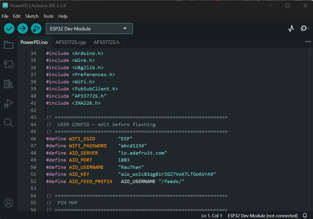
Add Adafruit IO Details in the Code
After setting up the feeds and dashboard, copy your Adafruit IO username and key.
Go to:
View Adafruit IO KeyThen update this part in the ESP32 code:
#define WIFI_SSID "your_ssid"
#define WIFI_PASSWORD "your_password"
#define AIO_SERVER "io.adafruit.com"
#define AIO_PORT 1883
#define AIO_USERNAME "your_aio_username"
#define AIO_KEY "your_aio_key"
Replace it with your own Wi-Fi and Adafruit IO details.

Step 7: Uploading Firmware

Folder setup
Create a folder named PowerPD and place all three files inside it:
PowerPD/
- PowerPD.ino
- AP33772S.h
- AP33772S.cpp
Open PowerPD.ino in Arduino IDE. Before compiling, update your Wi-Fi and Adafruit IO credentials near the top of the file:
#define WIFI_SSID "Your_WiFi_Name"
#define WIFI_PASSWORD "Your_WiFi_Password"
#define AIO_SERVER "io.adafruit.com"
#define AIO_PORT 1883
#define AIO_USERNAME "Your_Adafruit_IO_Username"
#define AIO_KEY "Your_Adafruit_IO_Key"
If you are not using Adafruit IO, you can leave these as dummy text. The local display and controls will still work normally.
Wiring the USB-to-UART converter
⚠️ Use a 3.3V logic level USB-to-UART converter. A 5V adapter will damage the ESP32.
USB-to-UARTPowerPD programming header
- TX RX
- RX TX
- GND GND
- 3V3 3V3
Entering download mode
The PCB does not have onboard BOOT and EN buttons. Use two small momentary push buttons connected with jumper wires:
- One button: BOOT pin → GND
- One button: EN pin → GND
Entering download mode
The PCB does not have onboard BOOT and EN buttons. Use two small momentary push buttons connected with jumper wires:
- One button: BOOT pin → GND
- One button: EN pin → GND
To enter download mode:
- Press and hold the BOOT button
- Press and release the EN button
- Release the BOOT button
- Click Upload in Arduino IDE immediately

After upload
Once the upload completes, press the EN button once to restart the ESP32. The OLED should show the PowerPD startup screen within 2–3 seconds.
Open the Serial Monitor at 115200 baud to see startup messages — this is the fastest way to confirm whether the AP33772S and INA226 were detected correctly.
Step 8: USB-C PD Chargers and Cables

The charger and cable you use with PowerPD matter more than you might expect.
Any USB-C PD charger starts at 5V by default. The AP33772S chip negotiates higher voltages by communicating with the charger over the CC lines — but it can only request what the charger actually advertises.
Before using any charger, check the label on the back. It should list the supported voltage and current profiles, something like: 5V/3A, 9V/3A, 12V/3A, 15V/3A, 20V/3A. A charger claiming 65W but only showing 5V/3A on the label will not give you 20V no matter what you request.
If you want to test PPS, specifically look for "PPS" printed on the charger or in its specifications. Not all high-wattage chargers support it.

The cable matters too. A poor quality USB-C cable can cause voltage drop, connection instability, or failed PD negotiation — making the board look faulty even when it is working correctly. For most testing, any USB-C to USB-C cable rated for 3A and PD is fine. For higher power loads near 20V and 5A, use an e-marked 5A cable.
Avoid USB-A to USB-C adapters, magnetic connectors, and unknown extension cables. Keep it simple:
USB-C PD Charger → USB-C to USB-C cable → PowerPD
Before connecting any load, always verify the output voltage with a multimeter first. This takes 30 seconds and rules out a lot of potential confusion.
Step 9: First Power-Up
Connect a USB-C PD charger using a quality cable. Do not connect anything to the V_OUT terminals yet.

When the charger is connected:
- The status LED should light up — this confirms VBUS is present
- The OLED should display the PowerPD startup screen within a few seconds
- The board reads the available PD profiles from the charger
- The output stays OFF

If the OLED stays blank, check your firmware upload. If the LED does not light up, check the USB-C cable and charger.

Once the startup screen appears, open the Serial Monitor at 115200 baud and confirm that the AP33772S and INA226 are both detected. Then check that at least 5V appears as a selectable profile on the OLED.

At this point the board is running on 5V (default). The output is OFF. Nothing is connected to V_OUT. This is exactly the right state to be in before moving to voltage testing.

Step 10: CAD Design

My Friend Mukesh designed the complete PowerPD enclosure in Autodesk Fusion with a focus on compact size, clean appearance, and easy assembly around the custom PCB.

The entire design consists of 4 main parts
1. Front_Panel:
This is the top cover/front section of the enclosure.
- Includes cutouts for the OLED display
- Holds the rotary encoder shaft and push buttons
- Provides openings for the USB-C connector and output terminals
- Also acts as the main top lid for the complete enclosure

2. Main_Housing:
The bottom housing securely holds the fabricated PowerPD PCB.
- Designed around the exact PCB dimensions
- Includes PCB mounting supports and screw points
- Provides access for the USB-C port and programming header
- Keeps the internal electronics protected and aligned properly
3. Rotary_Encoder_Knob:
A custom-designed rotary encoder knob made specifically for PowerPD.
- Easy to grip while adjusting voltage and navigating menus
- Compact design matching the enclosure style
- Push-fit mounting onto the rotary encoder shaft
4. PCB_Mounting_Layout:
The enclosure is designed so the assembled PCB can be mounted directly inside without extra brackets or wiring complexity.
- OLED header already aligns with the front panel window
- Rotary encoder position matches the knob opening
- Compact internal arrangement keeps the build clean and simple
I have attached:
- The original Fusion 360 design files
- STL files for all printable parts

You can:
- View and modify the CAD model in Fusion 360
- Adjust the enclosure dimensions if needed
- Directly slice and 3D print the provided STL files for your own build

Voltage Testing

With the board powered on and the output disabled, I used the rotary encoder to cycle through the available USB-C PD voltage profiles. The OLED display showed the supported profiles from the charger, including 5V, 9V, 15V, and 20V.
After selecting a voltage, I enabled the output and verified the actual V_OUT using a Fluke multimeter. The measured voltage matched the OLED reading very closely:

- 5V profile measured around 4.98V
- 16V PPS setting measured around 15.96V
- 20V profile measured around 20.07V
This confirmed that the AP33772S was correctly negotiating the selected PD profile and that the INA226 voltage monitoring was properly calibrated.
I also tested PPS mode by selecting adjustable voltage levels through the rotary encoder. The output voltage changed correctly and the multimeter readings matched the requested values shown on the OLED display.

Step 12: Load Testing

After confirming the voltage profiles were working correctly, I connected a few real loads to the PowerPD output for testing. Instead of using an electronic load, I tested the board with a 12V cooling fan and a high-power BLDC motor running from the selected USB-C PD voltage.
With the output enabled, the OLED display showed live voltage, current, and calculated power in real time. The Adafruit IO dashboard also updated wirelessly over Wi-Fi, showing the same live voltage, current, power, and temperature data remotely.

PD analyzer mode to monitor the charger negotiation process. The OLED can display the detected PD profiles, active voltage, PPS status, and real-time output information directly from the connected USB-C charger. I have attached a GIF below showing the live PD negotiation and analyzer interface in action.

After confirming the voltage profiles were working correctly, I connected a few real loads to the PowerPD output for testing. Instead of using an electronic load, I tested the board with a 12V cooling fan and a high-power BLDC motor running from the selected USB-C PD voltage.With the output enabled, the OLED display showed live voltage, current, and calculated power in real time.

The Adafruit IO dashboard also updated wirelessly over Wi-Fi, showing the same live voltage, current, power, and temperature data remotely.I also added a built-in PD analyzer mode to monitor the charger negotiation process.

The OLED can display the detected PD profiles, active voltage, PPS status, and real-time output information directly from the connected USB-C charger. I have attached a GIF below showing the live PD negotiation and analyzer interface in action.