
Very often, I receive a request from my viewers to explain the method of making the cases for my electronic projects. First of all, let me tell you that the cases are not made with 3D Printing, but from a special PVC material.
In fact, this is the secret to the beautiful appearance and versatility in the construction of these houses. I purchase this material from a local company for the production of illuminated advertisements and they simply call it PVC.
In fact, this is the secret to the beautiful appearance and versatility in the construction of these houses. I purchase this material from a local company for the production of illuminated advertisements and they simply call it PVC.
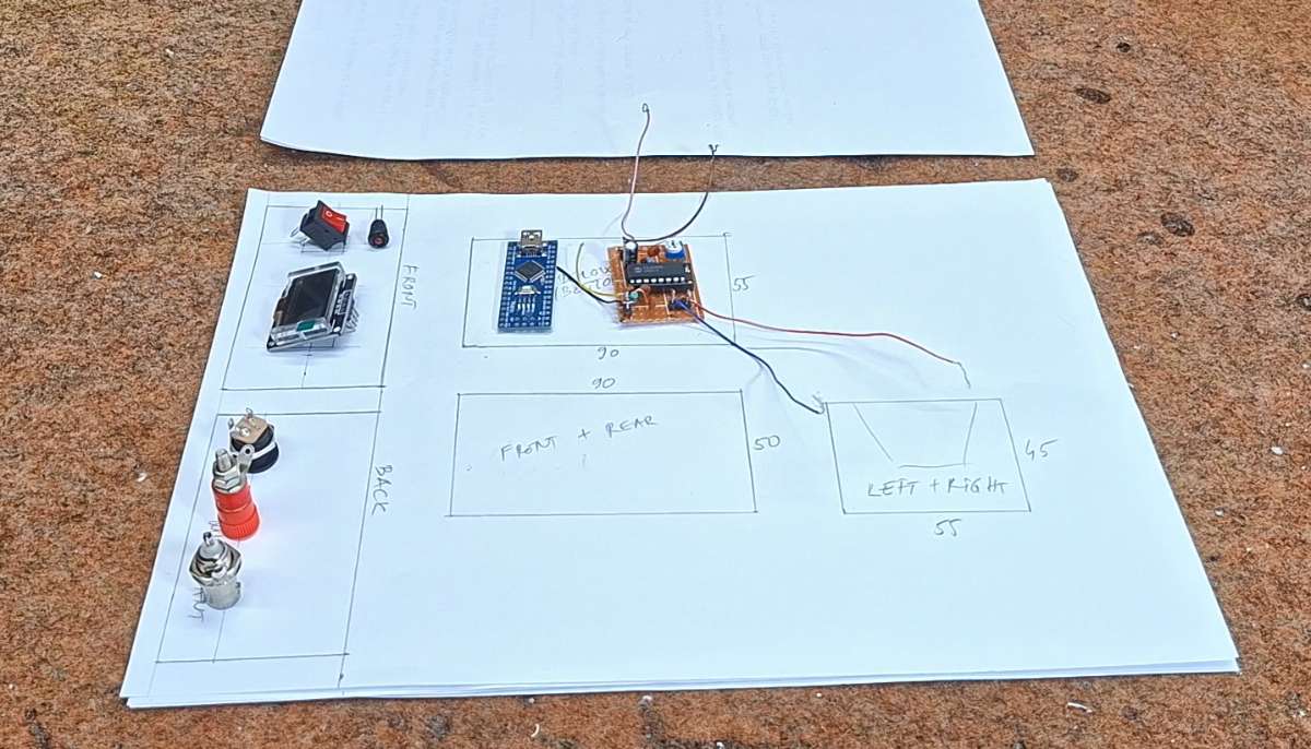
This time I will explain to you the making of the so-called "matchbox" housing, which is the most complex to make, but therefore the most practical. First, we need to determine the rough dimensions of the final box based on the components used in the assembly. In this case, I have a small PCB and an Arduino nano microcontroller, and on the front there will be an OLED display and a switch with an LED diode. On the back of the housing we need to have a power connector, an Antenna Input and a connector for connecting a regular wire. For easier access when installing the electronics, and possible service and adjustments (which is almost regular with DIY devices), we make the box with slightly larger dimensions than necessary. First we make a draft with dimensions on paper, and then we draw the pieces on the PVC material.
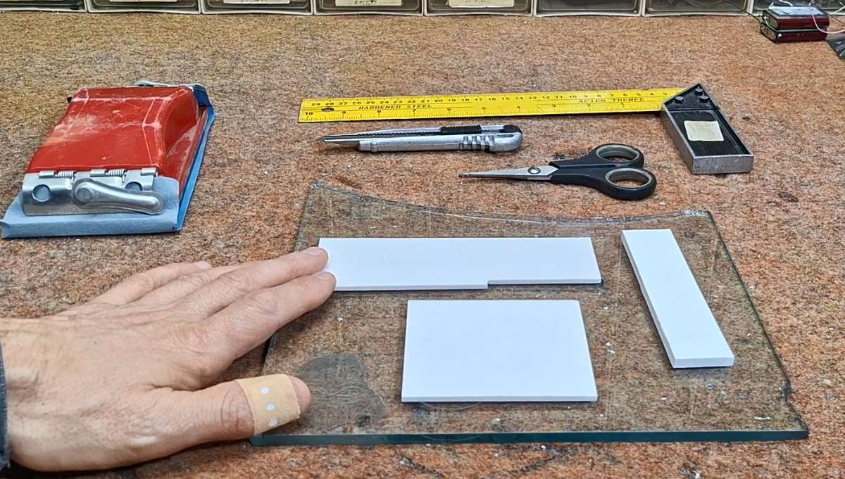
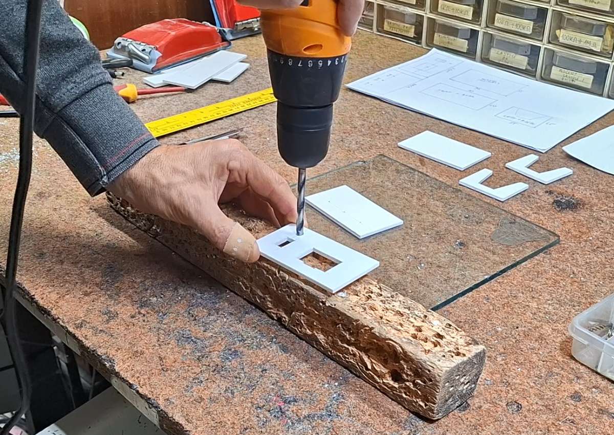
The inner part of the box is made of 3mm PVC. After we draw the parts, we move on to cutting them. Then we make appropriate openings on the front and back. The straight lines are cut with a hobby knife, and the round ones with a drill and similar woodworking tools.
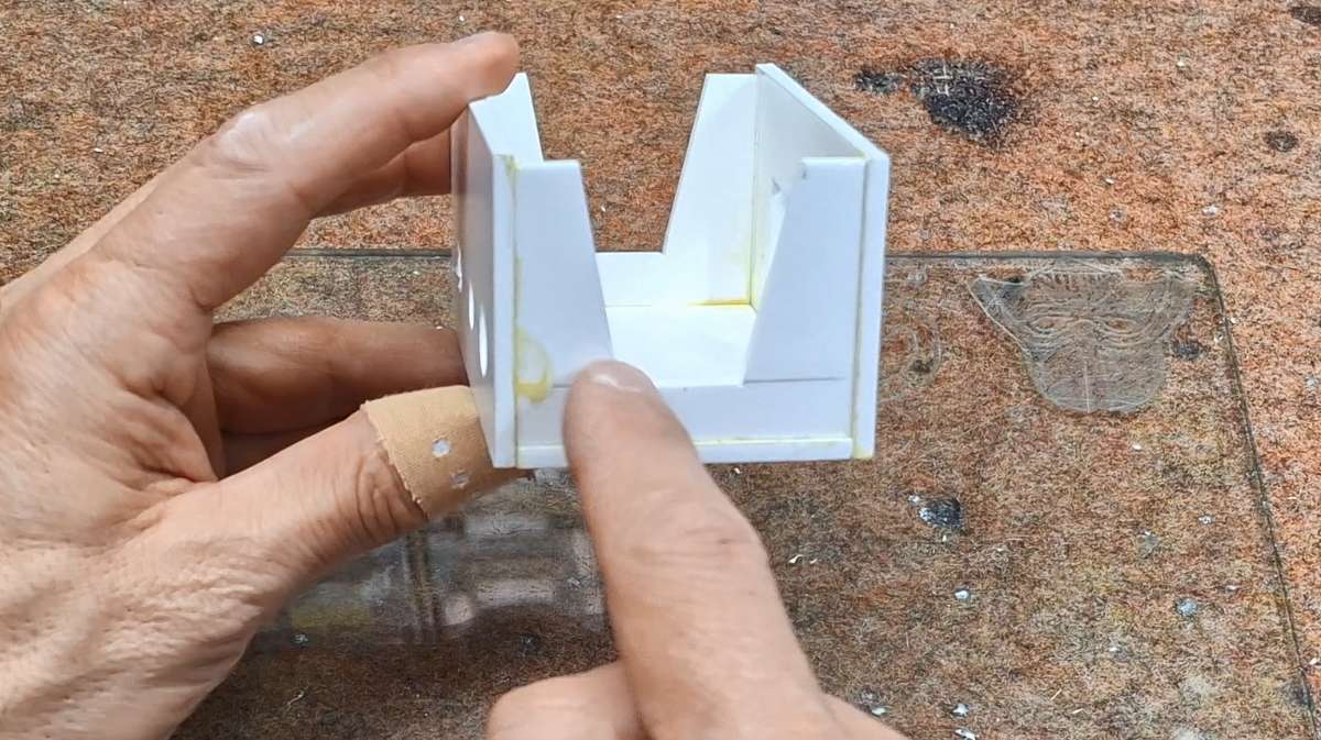
When we are done cutting, we slightly sand the edges and move on to gluing. For this operation, we can use one of the many universal glues, but it is not recommended to use super glue at this stage. This is what the finished inner part of the box looks like, in which the electronic assembly will be installed.
When we are done cutting, we slightly sand the edges and move on to gluing. For this operation, we can use one of the many universal glues, but it is not recommended to use super glue at this stage. This is what the finished inner part of the box looks like, in which the electronic assembly will be installed.
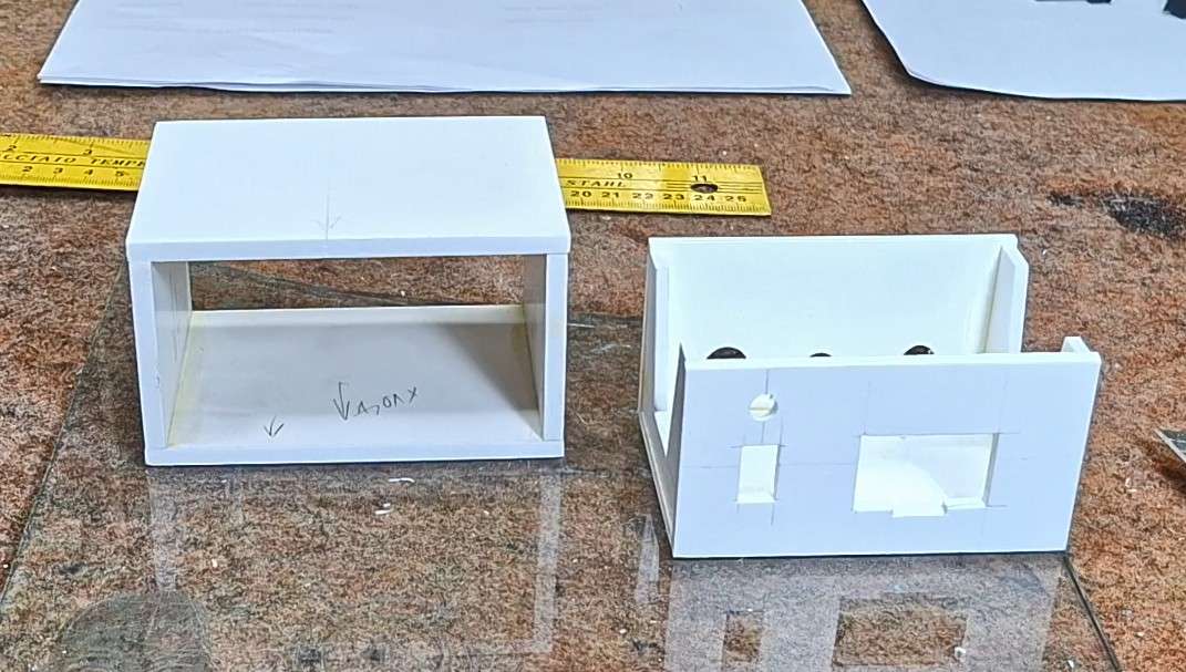
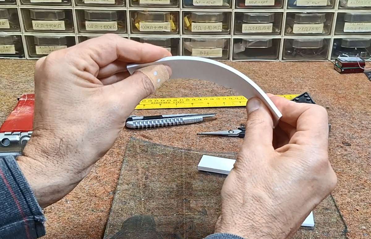
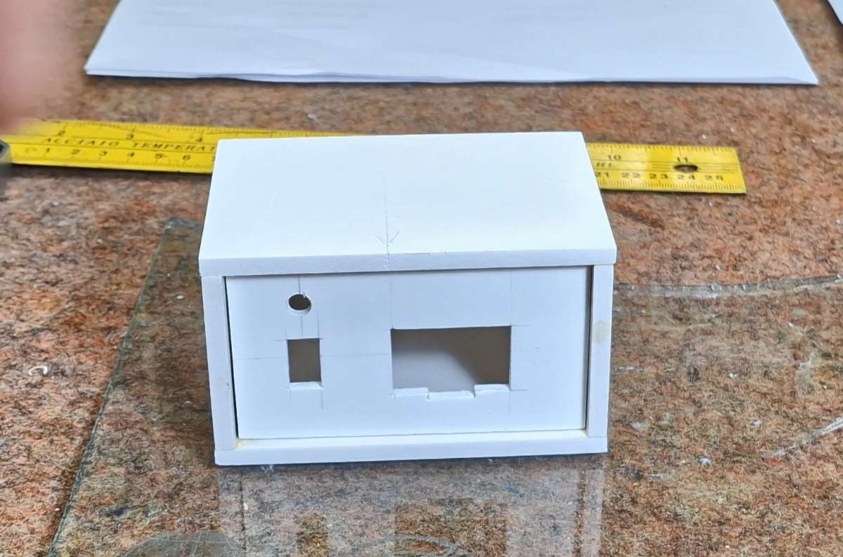
For a better visual impression, this part is made of thicker PVC board, specifically 5mm. We also sand this part and glue it with universal glue. Here's what the finished box should look like. The inner part should move freely within the armor.
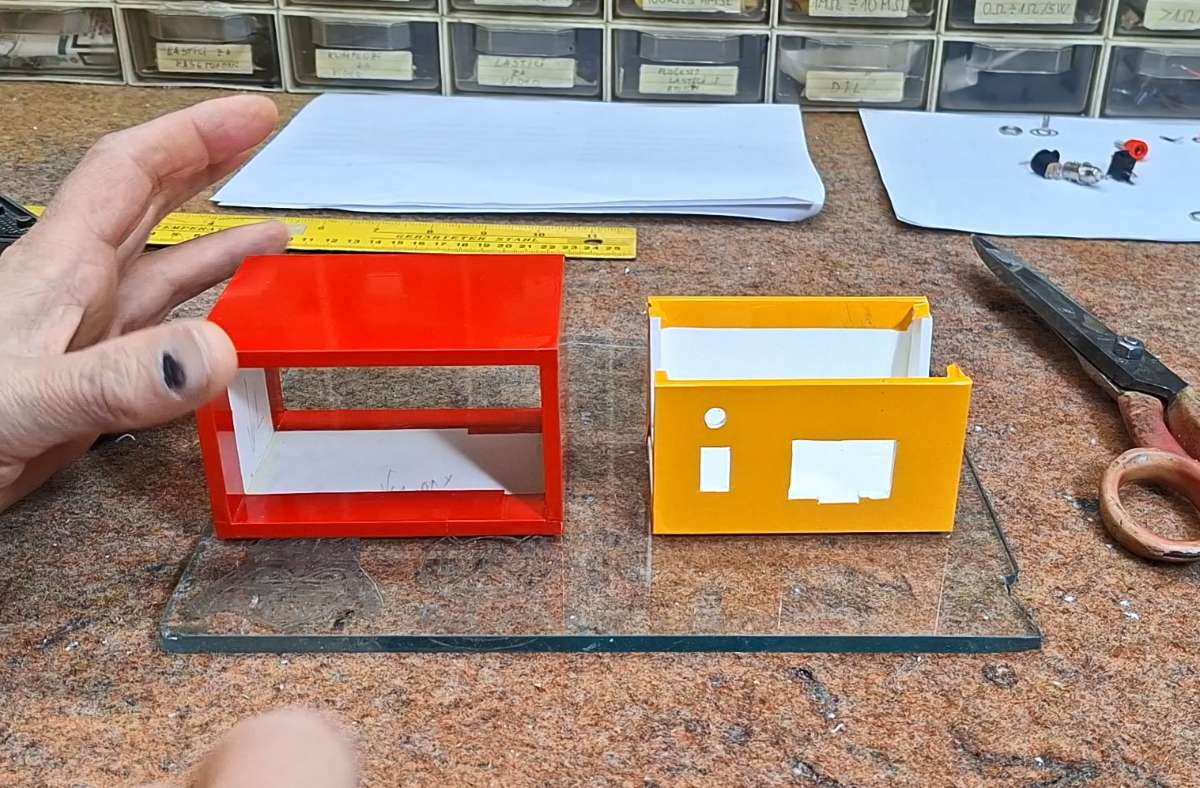
Next comes the covering of the box with self-adhesive wallpaper. Most often, the front and back of the box are covered with a lighter color (white or cream) because then the markings that will be printed need to be legible. We choose the color of the armor according to our wishes. Let me just tell you that sticking wallpaper requires a little more patience and experience that you will gain over time.
Now it's time to mount the electronic part inside the box. First, the elements on the front and back are mounted (in this case the switch with the LED, the Display, and the connectors on the back). Specifically, I will attach this small display on the back with double-sided adhesive, and on the front I will put a special mask, the making of which you will see below.
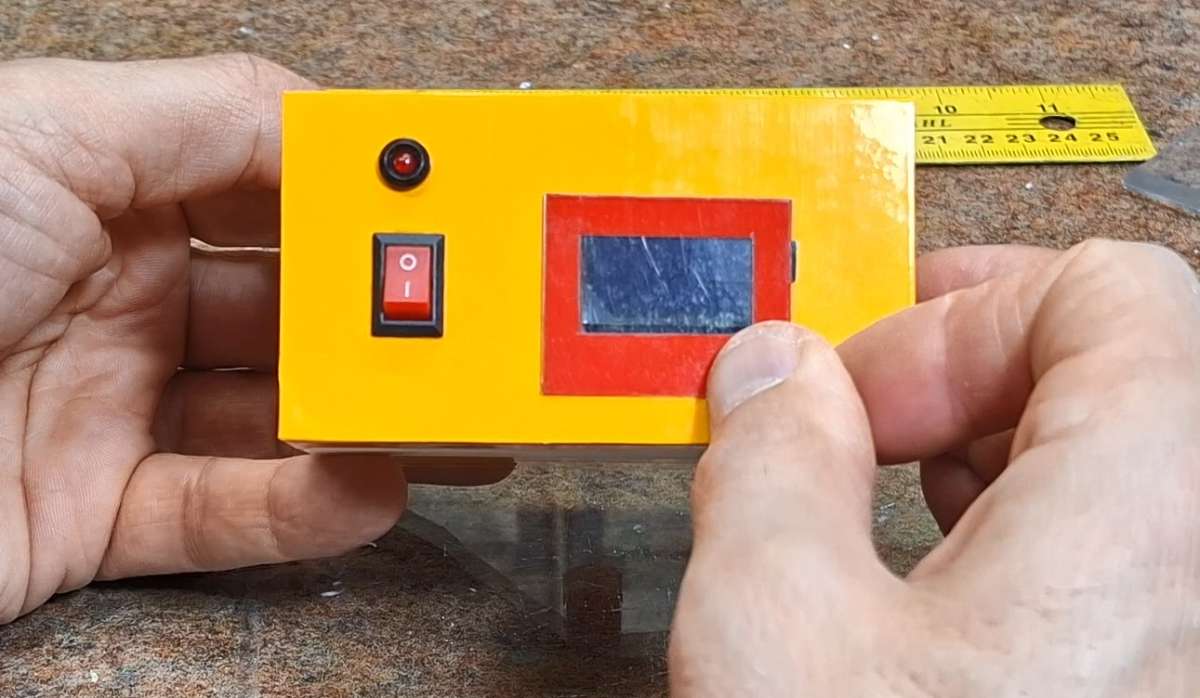
Now we attach the PCB in some way (the easiest way is with double-sided adhesive) to the bottom and make the appropriate connections with wires.
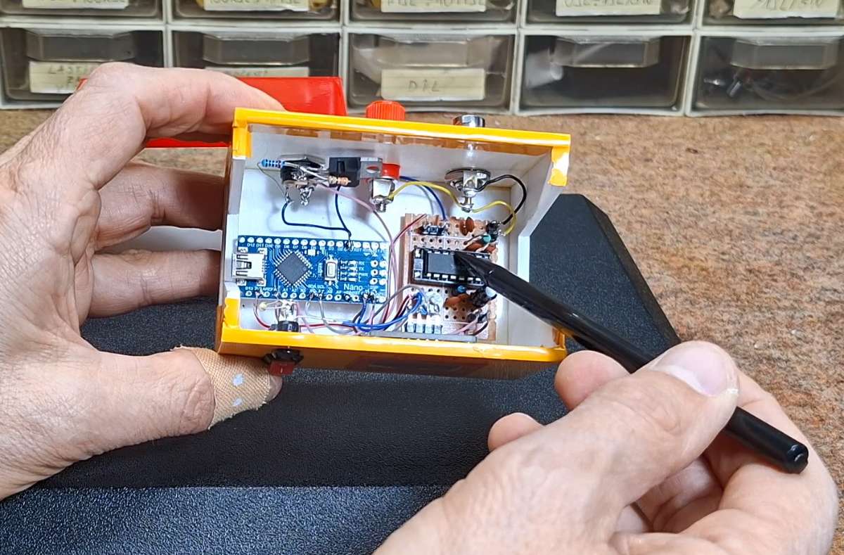
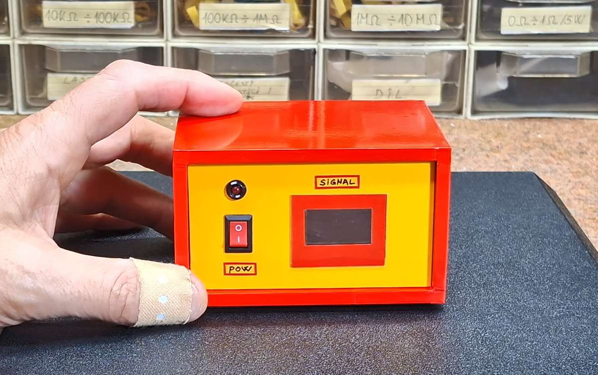
When soldering, we should be careful not to damage the wallpaper with the soldering iron. Then we test the functionality of the assembly and mount it in the frame. From the bottom, we fasten the frame to the box using two screws so that it does not move. We place appropriate carpenter's washers on the four edges. This is how the complete finished device looks in the so-called Matchbox housing.
In my projects I use two more types of simpler cases. The first is of this type, I usually use it for simpler assemblies or places where certain visual components need to be outside the case. Here we have a base on which a fence is glued and the top side is flexible and is mounted with a few screws.
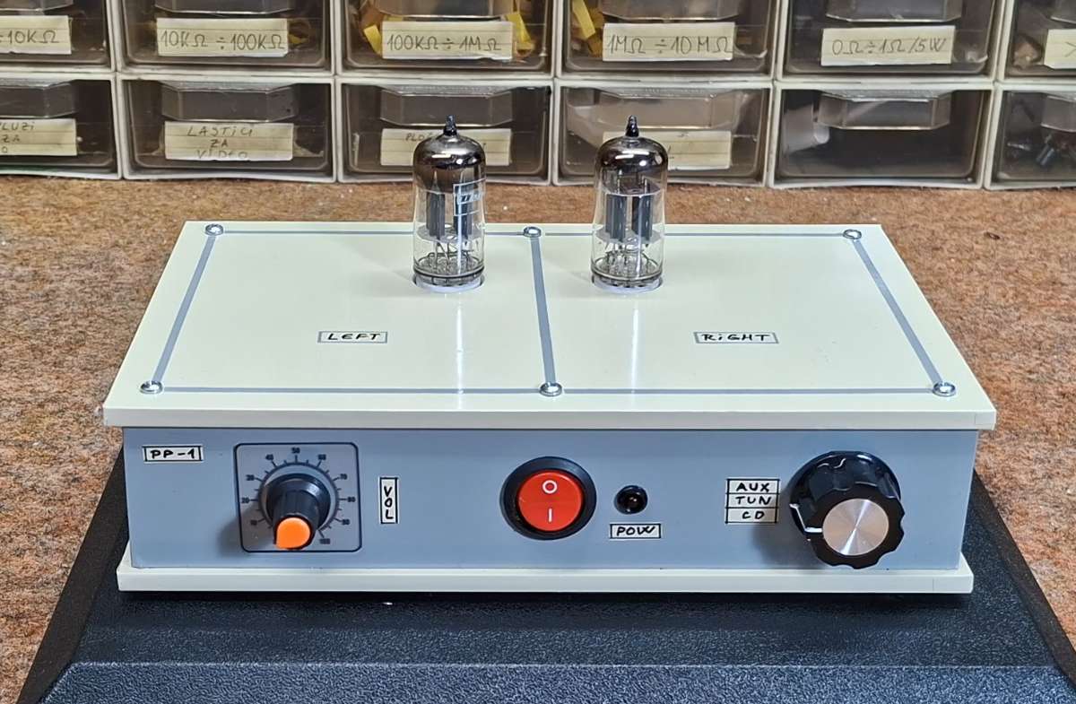
And finally, the simplest model suitable for demonstration conditions where we need to have a good visual effect (the front panel) but also complete instant access to the electronic assembly without the need for unscrewing or desoldering.
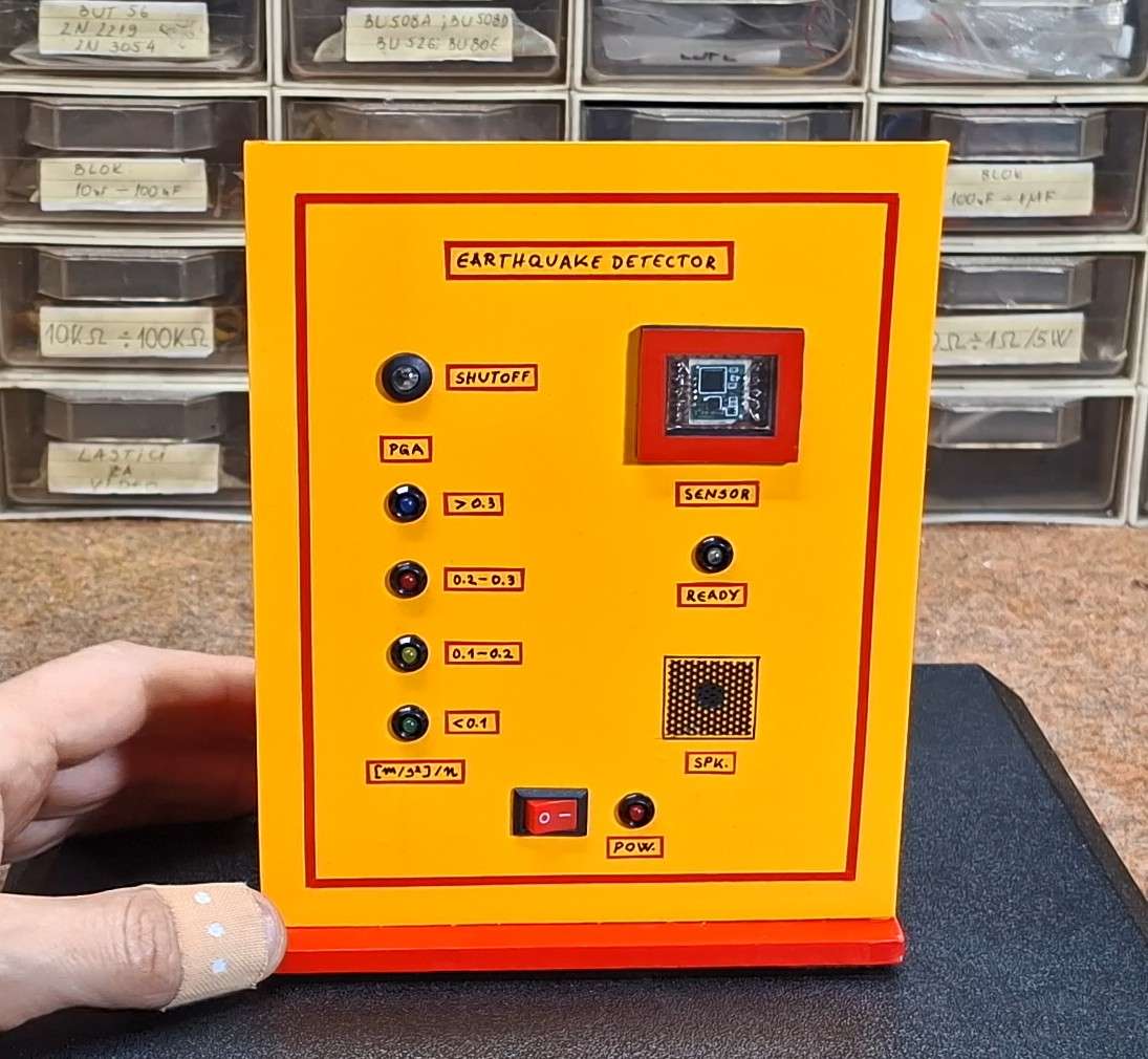
By following these steps, you can create professional-looking, durable housings that give your DIY electronics a polished and functional finish.