These days I accidentally came across this small retro Black and White TV with a built-in Radio, so I immediately decided to make some simple useful device with it. Of course, first I decided to check its current condition and functionality.
Let's examine the Radio receiver. As far as I can see, this part of the device is functioning normally and the only thing that needs to be cleaned is the volume potentiometer, possibly with some contactor spray.
Now let's move on to the TV receiver. In a few seconds, a white raster appears on the screen, which is a sign that this part of the device is probably completely functional. We still have to examine the tuner part, by bringing an analog signal to the antenna input. For this purpose, I will use the signal from cable television. This signal is in the VHF-III Band, so now I will start searching for channels.
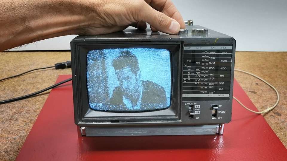
As I assumed, and the TV receiver is completely functional, but unfortunately nowadays it has no significant use value except as part of some retro TV collection.
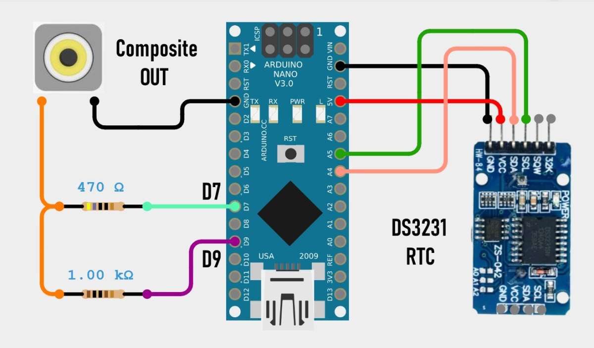
I got the idea to "bring back to life" this small cute device in a way that I would make some kind of clock that would display the time and date on the screen. And of course the most suitable for that purpose is the Arduino microcontroller together with the TVout library with the help of which a composite signal is generated through only two resistors.
The model of this device is "Inno-Hit TV128" but after a long search I was unable to find any service manual or circuit diagram. Many years ago I worked in a TV repair shop and I have relatively extensive knowledge in this area.
By definition the composite input should be located somewhere between the video amplifier and the sync section. After a detailed examination of the PCB and its components I discovered that the video amplifier in this case is TA7678AP IC and the sync section is µPC1379C IC.
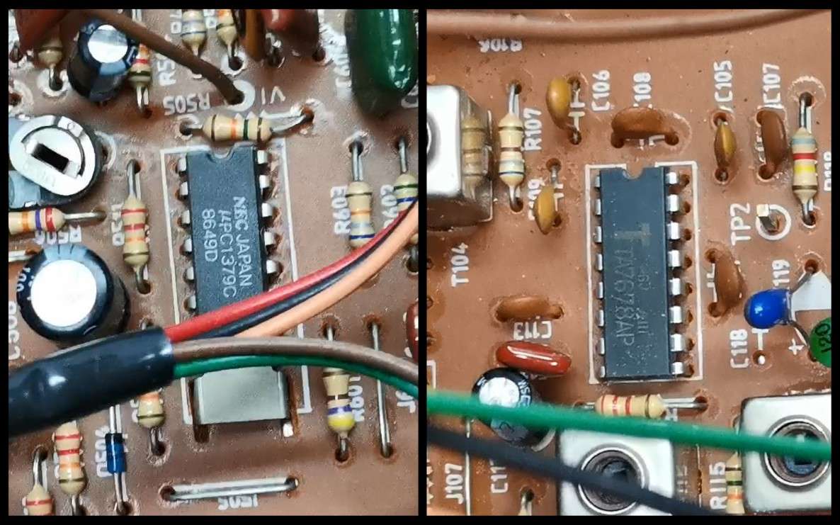
By definition the composite input should be located somewhere between the video amplifier and the sync section. After a detailed examination of the PCB and its components I discovered that the video amplifier in this case is TA7678AP IC and the sync section is µPC1379C IC.
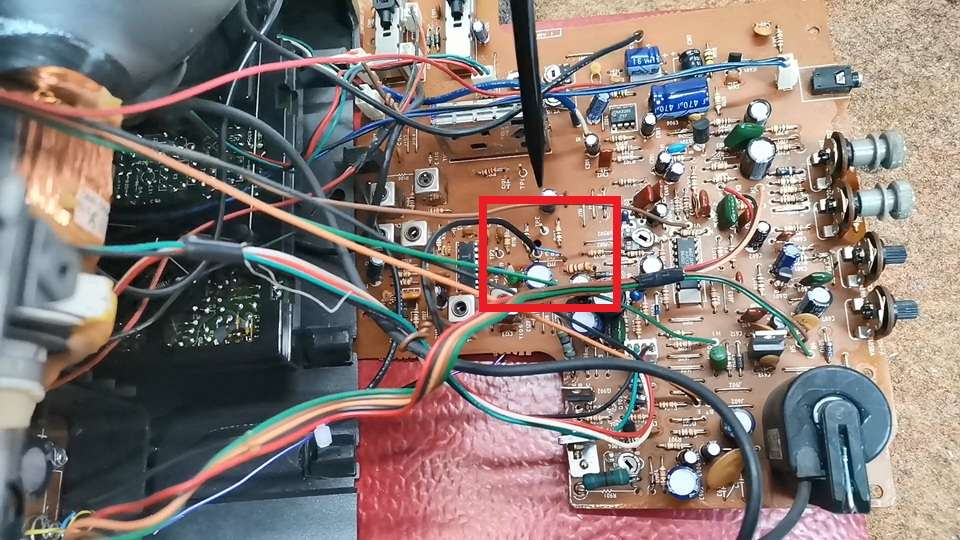
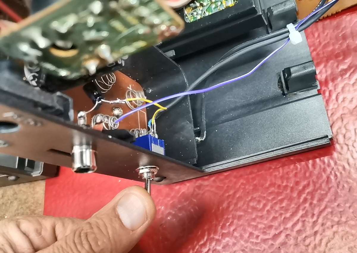
So I need to remove this jumper so that the previous tuner circuit does not affect the signal, and connect the composite input directly to the input of the sync section.
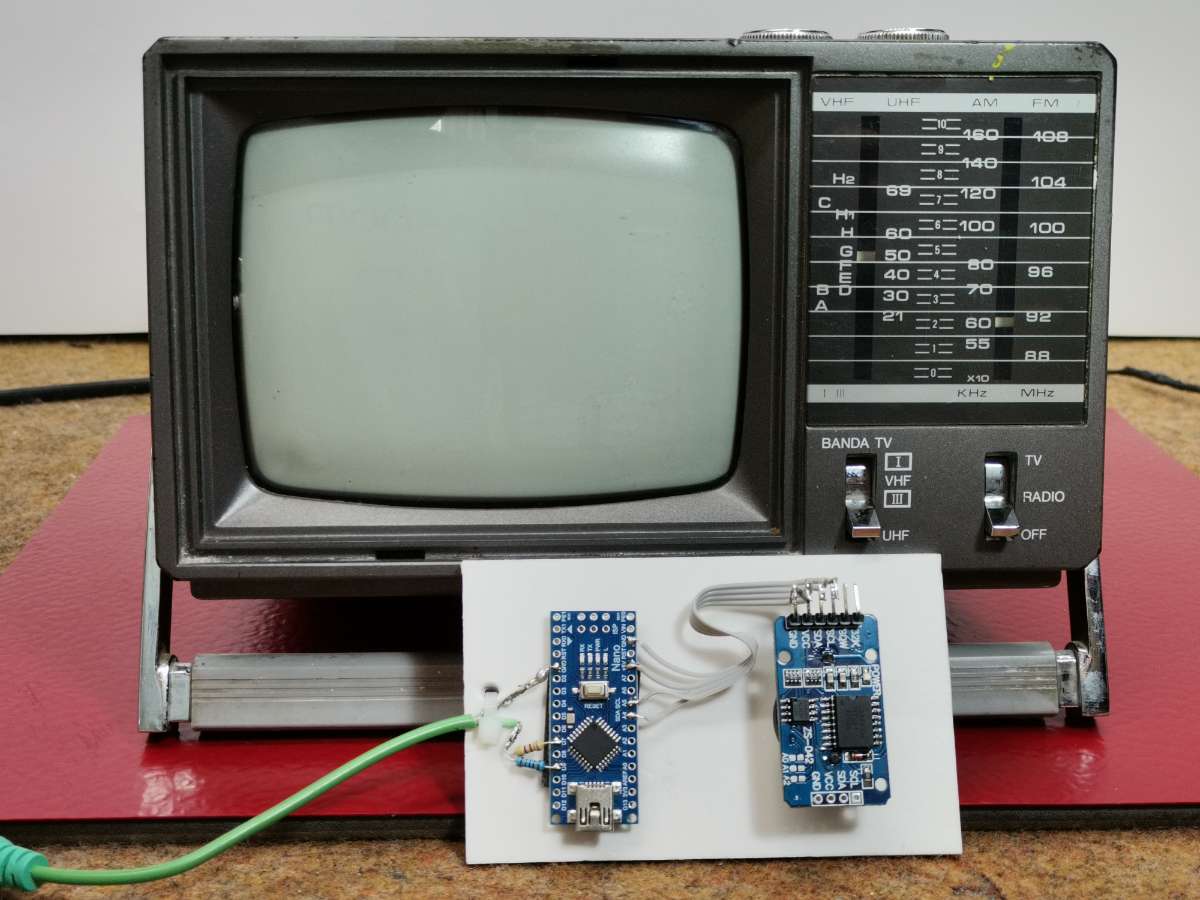
Composite signal generator consisting of an Arduino Nano and 2 resistors, and there is also the DS3231 real time clock module with a built-in battery from which the exact time is read and displayed on the TV screen.
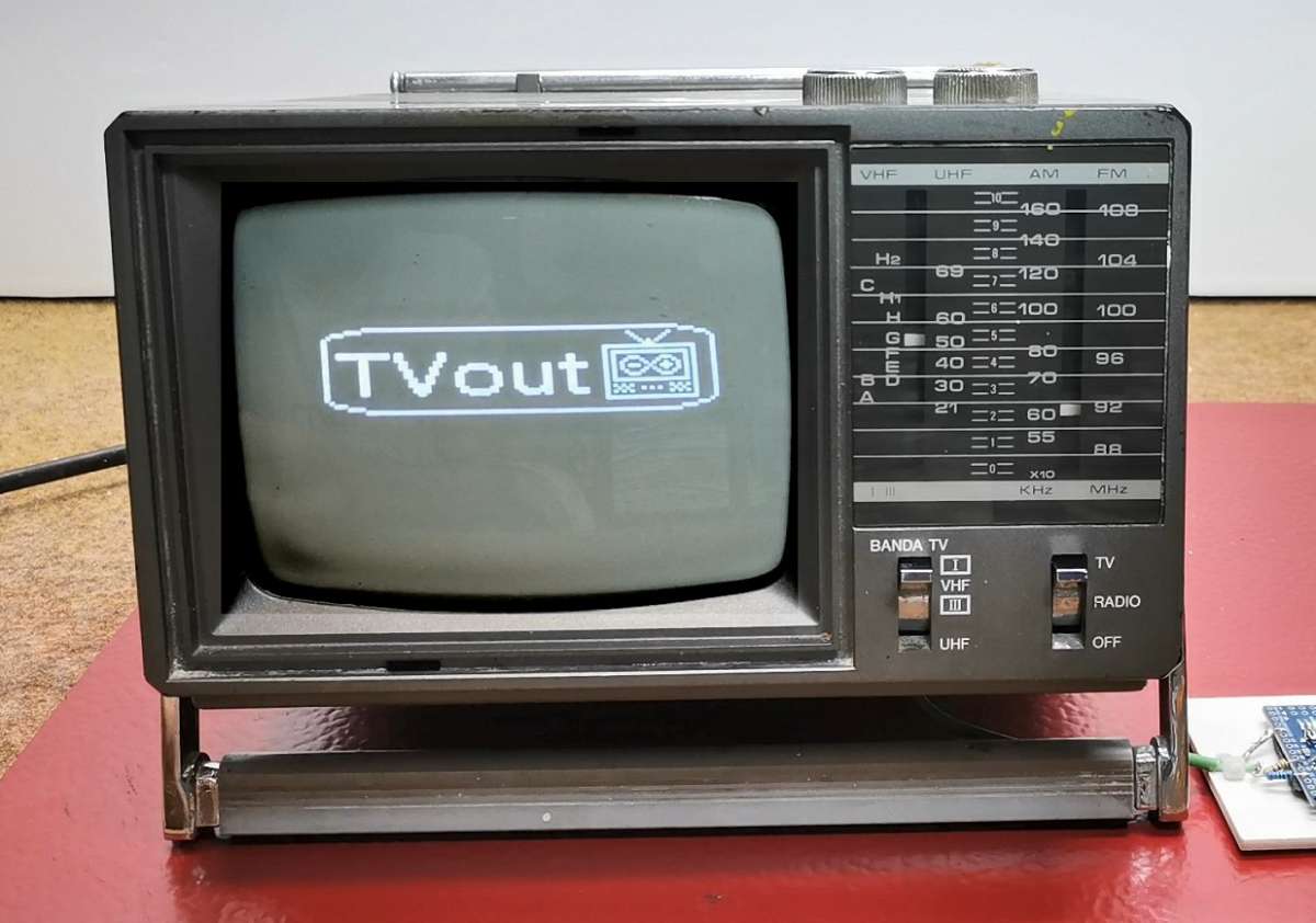
Now for testing I will send a demo signal, actually an example from the TVout library. One important note. If you install the TVout library by default via "manage libraries" or by copying it to the library folder, you will get the error "fontALL.h: No such file or directory" when compiling.
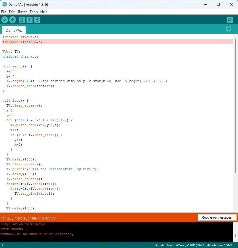
Now for testing I will send a demo signal, actually an example from the TVout library. One important note. If you install the TVout library by default via "manage libraries" or by copying it to the library folder, you will get the error "fontALL.h: No such file or directory" when compiling.
Understandably, now the BAND switch has no function because the tuner section has been omitted. Now you can adjust the brightness and contrast of the image and, if necessary, horizontal or vertical synchronization. And as I mentioned earlier, I created a relatively simple code that will display the time, day of the week and date in digital form. Initially, my idea was an analog clock but due to the extremely low resolution that can be generated by the Arduino, the image was desperately bad.
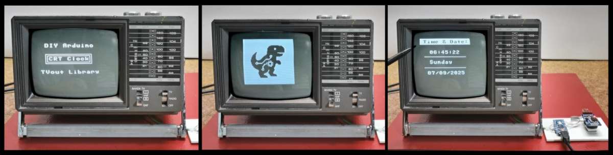
Understandably, now the BAND switch has no function because the tuner section has been omitted. Now you can adjust the brightness and contrast of the image and, if necessary, horizontal or vertical synchronization. And as I mentioned earlier, I created a relatively simple code that will display the time, day of the week and date in digital form. Initially, my idea was an analog clock but due to the extremely low resolution that can be generated by the Arduino, the image was desperately bad.
Understandably, now the BAND switch has no function because the tuner section has been omitted. Now you can adjust the brightness and contrast of the image and, if necessary, horizontal or vertical synchronization. And as I mentioned earlier, I created a relatively simple code that will display the time, day of the week and date in digital form. Initially, my idea was an analog clock but due to the extremely low resolution that can be generated by the Arduino, the image was desperately bad.