A function generator is a piece of electronic test equipment used to generate various types of electrical waveforms over a wide range of frequencies. It's an indispensable tool for anyone involved in electronics or electrical engineering for electronic design and testing. The most common waveforms produced are Sine, Square and Triangular wave.
A rectangular signal can be easily generated with discrete components, standard ICs, and microcontrollers, while for precise generation of sine and triangle waveforms are most often used specialized ICs. Such is the case here, where the XR-2206 specialized chip is used for this purpose, which, although a bit outdated, performs its function perfectly.
This is a cheap kit for making a function generator that costs less than $5 total. The kit contains all the necessary parts as well as a circuit diagram and can be made in less than an hour.
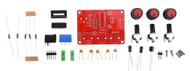
It also has an acrylic case, but in this case I will not use it and will make a larger case accordingly. Instead of the small onboard potentiometers I will put standard potentiometers, and instead of these jumpers I will mount switches on the front of the device.
This is an assembled and tested module that I soldered in a very short time and it works flawlessly the first time I turn it on.
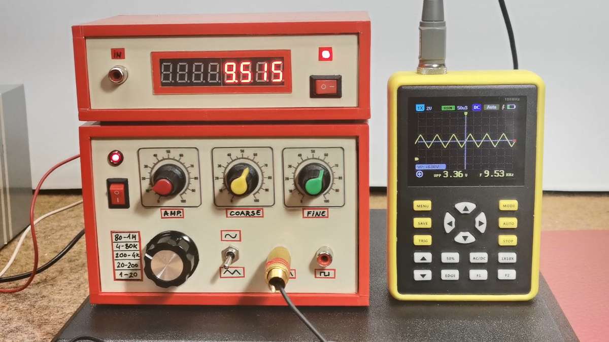
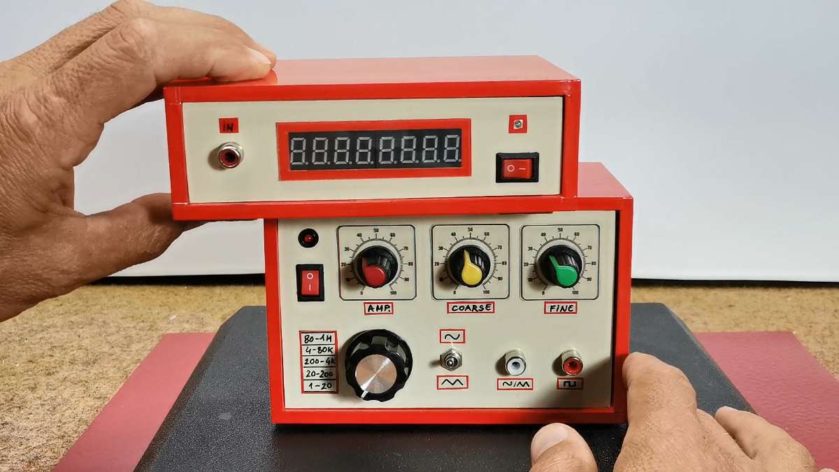
Here is what this module looks like mounted in a larger housing with a clear and easy-to-understand front panel for easier operation. I replaced the jumpers with a switch for selecting the frequency range as well as a switch for selecting between a sine and triangle signal on the corresponding output. Of course, there are also potentiometers for amplification, coarse and fine tuning of the generated frequency.
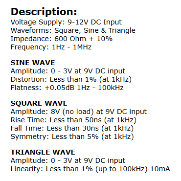
In short, the specifications of this device are: power supply from 9 to 12 Volts, sine and triangle waves with an amplitude of 0 to 3 V, and a rectangular signal with an amplitude of 8 Volts. Distortion and linearity of the signal are less than 1% up to 100 Kilohertz.
The device made in this way works great, but it has one big drawback, which is the inability to precisely adjust the frequency of the output signal. So I came up with the idea of using a device from one of my previous projects , which is actually a frequency meter, on which we will be able to read the exact set output frequency. Like the previous kit, this device costs about 5 dollars and consists only of an STM32 microcontroller and an 8-digit 7-segment display. Thus, the entire device will have professional features and will cost less than 10 dollars. You can watch the frequency meter project in one of my previous videos at the given link.
The frequency meter reads the rectangular shape of the signal most easily, so we will use this output from the generator. As I mentioned earlier, the generated rectangular signal has a constant amplitude of 8 Volts, so to adjust it to the level of the microcontroller, we simply use a small trimmer potentiometer in a voltage divider circuit.
Now let's see how the device works in real conditions. If we have connected everything exactly according to the instructions, the device works immediately and the selected frequency is displayed on the display.
.jpg)
Let me just remind you that the frequency reading is done every 500 milliseconds, so we have to wait a little while for an accurate reading. With the switch we select the range and with the coarse and fine potentiometers we precisely set the desired frequency. With the first potentiometer the amplitude of the sine and triangular signals is adjusted, and it must not exceed 3 volts to avoid signal distortion. The amplitude of the rectangular signal is constant and is 8V, but here too we can set a potentiometer and regulate the value.
Next, I will test the shape, amplitude, and frequency of the output signals using an oscilloscope to ensure the complete functionality of the device.