.jpg)
New update Source Code: 12/18/2024
"wifi satellite positioner" source code updated
In the new update, you connect to the positioner by connecting to your router's WiFi network.

1. Using your phone, connect to positioner wifi network
	Default SSID: Positioner
		PSK : 12345678

2. Using your phone browser, enter ip address URL: 192.168.1.1

3. Click wifi config, Add network.

4. Now, Using your phone, connect to Router wifi network.

5. then Using your phone browser, enter ip address URL: 192.168.1.184

New update board:
New design board with ESP-12f module was added in the attachments section.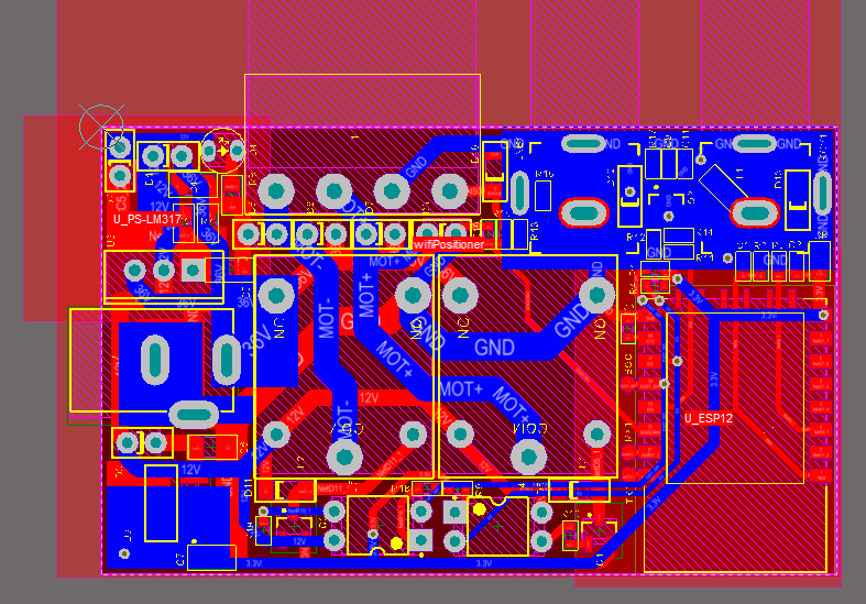
With the advancement of smart home appliances and the increasing use of them in today's human life, I thought it would be interesting to design a device that most of us have at home, that in this new design can be used like a smart device
So I chose the satellite dish positioner, its main function is to store the position of the satellites in memory and the ability to move to the satellite requested from the receiver.
Now, in this project, I tried to design a board that, in addition to the main task of the positioner, is connected to the network and can be setup and controlled through the network.
With this project, we will learn how to use the ESP chip and build a smart device instead of using the Wi-Fi module. In the source code section, we will learn to create the library we need and create the required classes according to the project objectives.
We connect to the board (web server) and that means sending http requests, so we will learn to create libraries that display web pages and use Ajax on the web page to instantly display the counter without refreshing the web page.
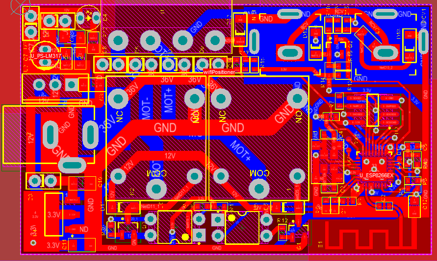
hardware
The main part of the board is the use of the ESP8266EX chip. It's a SoC (System on Chip), with IoT (Internet of Things) and deep sleep capabilities. The ESP Controllers from Espressif are becoming a widely popular choice for IoT based designs.
I did not use the ESP8266 module and tried to design with the ESP8266EX hardware design guide at the chip level on the PCB.
The board consists of several main parts, which include:
- DiSEqC Detector
- Motor driver which includes two relays, transistor and optocoupler
- Dish motor sensor counter detection
- ESP8266EX chip that: DiSEqC data processing and according to DiSEqC commands performs the relevant function. (Save satellite position - start the motor - stop the motor, etc.). Connect the board to the Wi-Fi network
- 24 to 12 V regulator and 3.3 V regulator that supplies power to different parts of the board
Note: The board requires a 24 volt 2 amp adapter.
Electronic circuit diagram
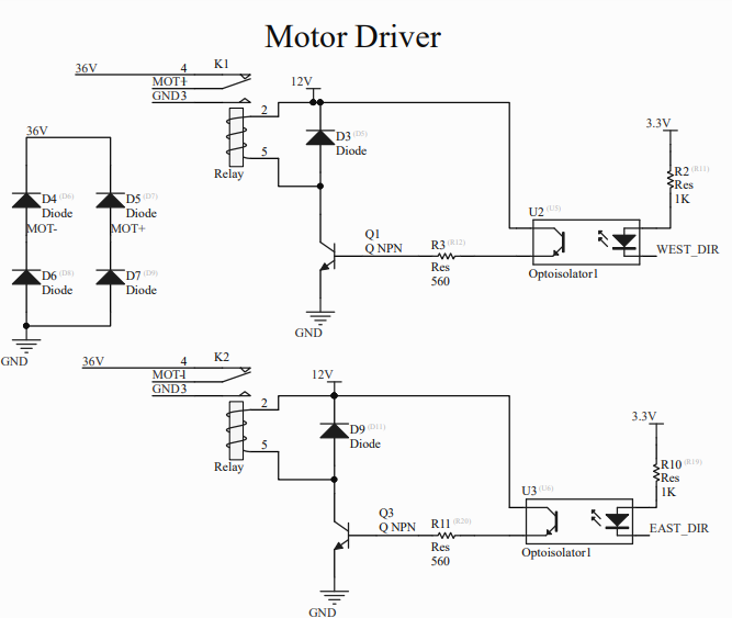
- MOTOR Driver circuit diagram
The motor driver consists of two relays, a transistor and an optocoupler. Two relay pins are used that turn the motor in two different directions.
MOT- and MOT + are connected to the motor.
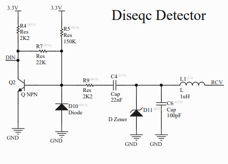
- DiSEqC circuit diagram
The figure below shows a basic receive-only circuit (i.e. with no reply facility), as might be used in a Low Noise Block (LNB) or Switcher.
The Intermediate Frequency (about 1 - 2 GHz) on the coaxial cable (downlead) is isolated from the Slave’s circuitry by a track on the Printed Circuit Board which is a quarter-wavelength long and “shorted” by a capacitor of typically 100pF. The nominal 650 mV., 22 kHz tone on the bus is amplified by the transistor to drive the ‘TTL level’ input (DIN) of the microcontroller.
The component values shown have been chosen so that the Slave does not respond to signals below about 300 mV. This can be beneficial because some LNBs are known to inject spurious noise or oscillations onto the cable, and devices such as Positioners may put an undulating power drain on the bus. However, some designers may prefer to use somewhat higher gain amplification to improve reception in conditions where an excessively high capacitive load is present on the bus.
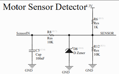
- Reed relay sensor circuit diagram
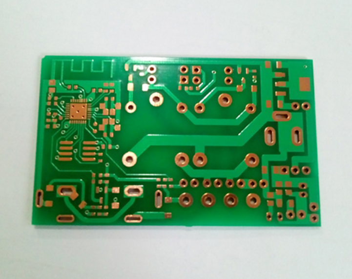
Printed circuit board (PCB)
To build this project, you must first prepare the board. Print and assemble the schematic and pcb files attached at the end of this post, then we will upload the firmware to the hardware.
After completing the hardware, you must open the source code file of the project on arduino and upload the firmware on the hardware.
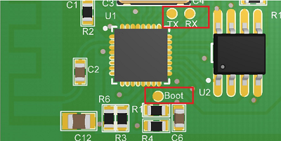
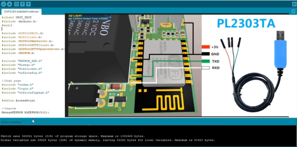
Note: The upload is done for the first time through the serial port, and to do this, you must connect the USB to serial to the boot pads on the board (shown in the figure below) and for the next time, the firmware can be uploaded through the Wi-Fi network.
Version1:
Version2:
Source code
The program code is written with the Arduino framework and in the PlatformIO ecosystem. PlatformIO is an open source ecosystem for IoT development with a cross-platform build system, a library manager, and full support for Espressif (ESP8266) development.
Several new libraries have been used for this project, which I have written myself, including libraries:
- Diseqc.h
- Positioner.h
- wificonfig.h
- EEPROM_ADD.h
We connect to the board (web server) and that means sending http requests, so we create libraries that display web pages and use Ajax on the web page to instantly display the counter without refreshing the web page. libraries written for the web page include:
- index.h
- wificonfigPage.h
After completing the hardware and uploading the firmware on the hardware, it is time to run and test.
For the preliminary test, all you have to do is turn on the board and connect to it via Wi-Fi. With this test, you can evaluate the Wi-Fi connection and control relays to change the direction of the motor.
To do this, we need a 24-volt adapter to turn on the board.
Run and test
In the next step, after turning on the board, refer to the Wi-Fi section of your phone. Positioner must be added to the Wi-Fi list. Select it. The default Wi-Fi password of the device is 12345678.

When you have successfully connected to the device Wi-Fi, scan the above QR code to open the address 192.168.4.1 in the browser to open the device settings page. First, you need a username and password to enter the setup page.
.png)
The default username and password is "admin". Enter it in both boxes and sign in.
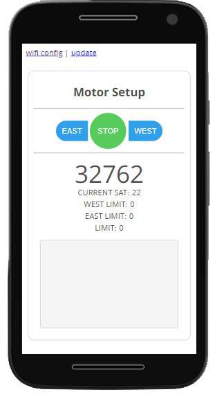
In the setup page, with the WEST - STOP - EAST buttons, you can start the dish motor to move. Below it is a counter that changes with the movement of the dish motor.
At this point, just touch the buttons to activate the relays on the board.
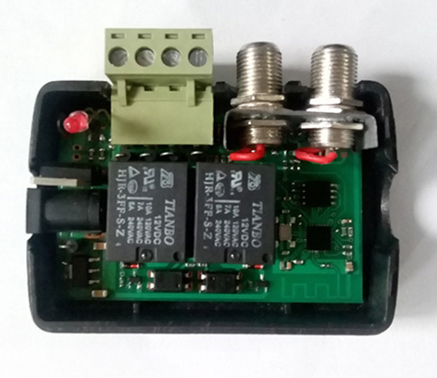
In the complete testing phase, the DiSEqC detector part is evaluated. The correct way to connect the board is shown in the figure below. Make sure the device is turned off before connecting.
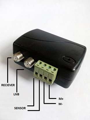
Now, go to the settings of Motor DiSEqC with the remote control of the receiver and select west or east there. The drive motor must start moving when selecting west and east.
github link: https://github.com/mehdi-adham/Arduino-Satellite-positioner-with-DisEqC-and-Wifi
Here are three videos on how to connect the positioner to the dish motor and receiver and test with Wi-Fi and remote control.
How to Program WiFi Satellite Dish Positioner Board with Arduino
Test with WiFi and remote control
How to connect positioner to motor and receiver