
Hi There,
There are numerous seven segment displays found in the market, so what is the difference in my project then? Well, I call my display the "Moodiest Display" which works on the popular WS2812B LEDs that are addressable and run on either 3.3v or 5v with a built-in WS2811 integrated chip. So, the assembly of the display is easy and filled with fun.
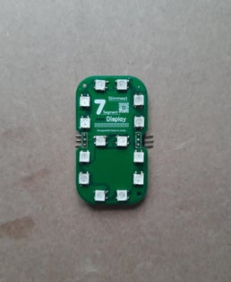
This is how a Fully Assembled Moodiest Display Looks like.
1. Proceeding with the WS2812B LEDs -
Each WS2812B LED has a data input and output pin. So, these LEDs take a formation of a Train where you connect the first LED to the data pin of the microcontroller, and the output of the first LED is connected to the data input pin of the second LED. The chain formation goes on...
Now the reason to choose WS2812B is that it has a built-in WS2811 integrated chip. We need a 100nF capacitor for each LED, but in this project, we can ignore it as we have a 3V option in the popular Nodemcu.
In the future, we can opt for a WS2813 LED as we get a built-in capacitor with the WS2811 integrated chip.
2. How to get the PCBs then?
Well, PCB stands for "Printed Circuit Boards" that need to be quality assured and fabricated with genuine materials to support your electronics. I thanks Lion Circuits for their IPC Graded class 2 PCBs for only a few dollars with on-time shipments.
Lion Circuits(Salient Features)
* have a Real-Time Pricing Engine.
* provide Instant DFM feedback pre-manufacturing.
* bring you AI-based Quality assurance with the latest AOI.
* secure your design in a robust Design Confidentiality environment.
Your PCB manufacturing time takes only 24 to 48 hours excluding the DFM check and the fastest global shipments.
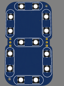
3. Designing the PCB
You might be thinking that how can we actually design such displays with only 6 pins in total ( 3 for DIN, GND, VCC, and 3 for DOUT, GND, VCC )
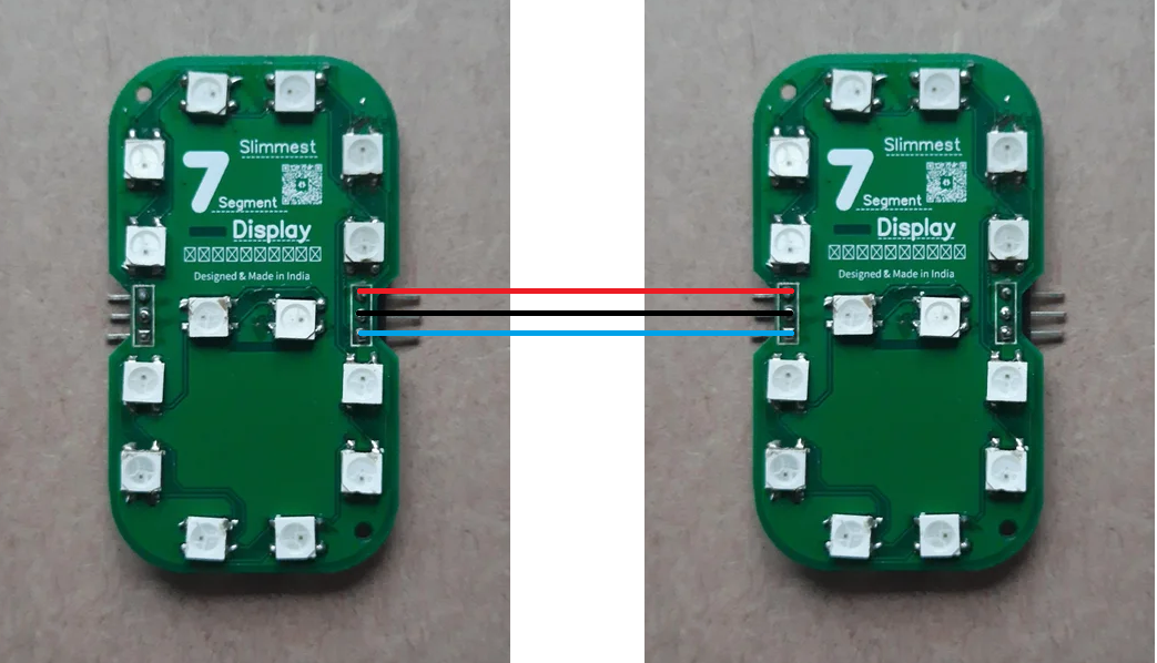
A crazy feature here is that these displays can be connected serially with each other like this -
So, my PCBs weigh less and have precise dimensions. Because the PCB is milled avoiding Board beneath the soldered LED.
I opt for female headers for the output pins and Male headers for the input pins as this will cascade our segments in daisy chain formation easily with no problems. Also, this design is small and precise to fit in your small walls.
The rest file parameters are as follows -
1. Track Width - 0.254mm
2. Track Clearance - 0.152mm
3. Via diameter - 0.61mm
4. Via drill Diameter - 0.305mm
5. PCB layers - 2 layer
6. PCB appearance - Green with White silkscreen + HASL surface finish.
4. Running these displays with code
So, to operate these displays there are tons of code available around the world, so to avoid complexity I prepared a code (From Kitesurfer's WS2812FX) for the initial test of this project which will help us know that what we have assembled is correct or wrong.
Now copy-paste the code into your Arduino IDE software and make sure you change your Wi-Fi credentials before compiling.
After uploading the code-
1. Open Serial Monitor in the Arduino IDE.
2. Wait for the message "connected"
3. Copy the IP address shown on the serial monitor and paste it into your browser.
4. Now you can control the segment from the browser over the air.
When we deal with the NeoPixels, there are chances of damaging the data pins while hand soldering.
So before soldering, upload the code to the microcontroller.
Then connect the Microcontroller with the PCB using jumper wires and check the effect after soldering.
This process will be time-consuming. But you will see a good result. The same I followed when I faced these errors.
Once you see the effect on a segment from the test code, you can develop your own code or get it from GitHub and hit upload.
Now there are some precautions to be followed -
1. Make sure the Data Pin defined in the Code matches your wired connection.
2. Make sure you have all the required libraries and the boards installed.
3. The VCC on the PCB requires 3V, not 5V.
I have shared the code here with proper credentials, just change your wifi details.
5. Customizations and some uses!
We are after the project now. You are ready with your Segment, Now let's discuss some future improvements.
Customization
So, what can the future versions come with?
1. We could have a version as a shield for the Raspberry Pico or the ESP32 Dev board.
2. We could have Battery management support to make the display portable.
3. We could even have a Touchpad system integrated with the display.
4. We may even switch to WS2813 NeoPixels which can be driven with 5V directly.
5. We will have a sensor integrated system for these segments shortly. Stay Tuned.
Uses
So, I have shared a youtube video here where you can see that how we can display numbers or use the display as a wifi-strength tester.
Check the code for this also that I have attached here!
Well, you can buy this project on My Store! This will help me get some stuff for my next project, your support is always incredible for me.
Also, you can check the important links on my linktree.
Thank you for your eyes on this project, hope you loved it. Now it's your time to show me your build! Have any doubts or queries? Drop a comment below and I will be really happy to solve them at the earliest.
Thanks for your support, hit a like on my first blog on ElectronicWings.
Till then stay safe, stay tuned, and get vaccinated if you aren't yet.