Mine Detection Using Autonomous Swarm Drones
A fully autonomous four-drone swarm for aerial landmine detection using YOLOv11 and GPS-tagged reporting
1. Introduction
Landmines remain one of the most dangerous post-conflict hazards worldwide. Manual detection is slow, hazardous, and expensive. This project presents a fully autonomous swarm of four drones — one Leader and three Followers — capable of surveying large open areas, detecting buried mine-like objects using a trained deep-learning model, and logging precise GPS coordinates of each detection without any human entering the danger zone.
The entire system is designed around commodity hardware: Raspberry Pi 5 companion computers, Braahma H7 ArduPilot flight controllers, ESP32 wireless modules, and Pi Camera Module 3 units. All software is written in Python and runs without any cloud dependency.
| CORE IDEA | One operator points in a direction using a hand gesture. All four drones take off, form a sweep line, fly 100 m in that direction, scan the ground with AI, geo-tag every mine found, and land automatically. |
1.1 Why a Swarm?
A single drone covers a narrow strip per pass. Three follower drones flying side-by-side at 6.67 m lateral spacing multiply the effective sweep width by approximately 3×, cutting total survey time for a fixed area by the same factor.
1.2 Why GPS?
A YOLOv11n model fine-tuned on mine imagery detects objects in each camera frame. The pixel position of every detection is converted to real-world GPS coordinates using the drone's altitude, camera field-of-view, and magnetic heading. A 2 m GPS-radius deduplication algorithm merges repeated sightings of the same mine into a single averaged coordinate, producing a clean, accurate mine map at mission end.
2. System Overview
2.1 Automated Mission Phases
| Phase | Actor | Description |
|---|---|---|
| 1 — Takeoff | All drones | Drones arm and climb to 3 m hover altitude. |
| 2 — Formation | Leader + Followers | Followers GPS-navigate to positions: 3 m behind leader, ±6.67 m lateral. |
| 3 — Gesture Input | Leader only | Pi Camera reads operator open-palm gesture to select flight direction. |
| 3.5 — Climb | All drones | Climb to 5.1 m mission altitude for optimal mine-camera ground coverage. |
| 4 — Forward Flight | All drones | Fly 100 m in chosen direction at 1 m/s. Followers run YOLO mine detection. |
| 5 — Hover | All drones | 15-second hover. Followers transmit mine GPS data to leader via ESP-NOW. |
| 6 — Land Followers | Leader commands | Followers land. Leader waits for all MINE_DONE confirmations. |
| 7 — Leader RTL | Leader | Leader returns to launch. Full CSV mine report saved to disk. |
2.2 Communication Architecture
All drone-to-drone communication uses ESP-NOW — a lightweight, connectionless 2.4 GHz protocol by Espressif. Each Raspberry Pi connects to an ESP32 module via UART at 115200 baud. The ESP32 acts as a transparent wireless bridge so the Pi only sends and receives plain text messages.
| Direction | Messages |
|---|---|
| Leader → Followers | ARM, TAKEOFF, FORMATION, HEADING:<deg>, START_MOVE, STOP_MOVE, LAND |
| Followers → Leader | READY, STATUS:<data>, MINE:<lat>,<lon>,<conf>, MINE_DONE |
| Heartbeat | Followers send periodic heartbeat. Leader triggers emergency land on timeout (10 s in air). |
3. Hardware Components
3.1 Components List (identical across all four drones)
| # | Component | Specification | Role |
|---|---|---|---|
| 1 | Quadcopter Frame | 250–350 mm wheelbase | Structure |
| 2 | Raspberry Pi 5 | 4 GB RAM, 64-bit ARM | Mission computer / AI inference |
| 3 | Braahma H7 FC | STM32H7, ArduPilot firmware | Flight control + MAVLink |
| 4 | GPS Module | M10 or M8N, 10 Hz update | Position and heading source |
| 5 | ESP32 Dev Board | ESP32-WROOM-32 | ESP-NOW wireless mesh |
| 6 | Pi Camera Module 3 | 12MP IMX708, HFOV 66° | Mine detection (downward-facing) |
| 7 | Brushless Motors | 2205–2306, 2300–2450 KV | Propulsion (×4) |
| 8 | ESC | 30–35A BLHeli32 (×4) | Motor speed control |
| 9 | LiPo Battery | 4S, 3000–4000 mAh, 45C+ | Power supply |
| 10 | Passive Buzzer | 3.3V, small PCB module | Audio status feedback |
| 11 | microSD Card | 32 GB Class 10 / U3 | OS + captured image storage |
3.2 Software & Libraries
| Library / Tool | Version | Purpose |
|---|---|---|
| Python | 3.11 + 3.13 | Primary language (two versions needed on leader for camera pipeline) |
| DroneKit | 2.9.x | MAVLink / ArduPilot high-level Python API |
| pymavlink | 2.4.x | Low-level MAVLink message encoding |
| Picamera2 | 0.3.x | Raspberry Pi Camera Module 3 driver (Python 3.13) |
| OpenCV | 4.8+ | Image capture, colour conversion, frame saving |
| Ultralytics YOLO | 8.x (v11n) | Mine object detection inference on-device |
| MediaPipe | 0.10.x | Hand landmark detection for gesture input (Python 3.11) |
| lgpio | 0.2.x | GPIO buzzer control (Pi 5 compatible, replaces RPi.GPIO) |
4. Circuit Connections
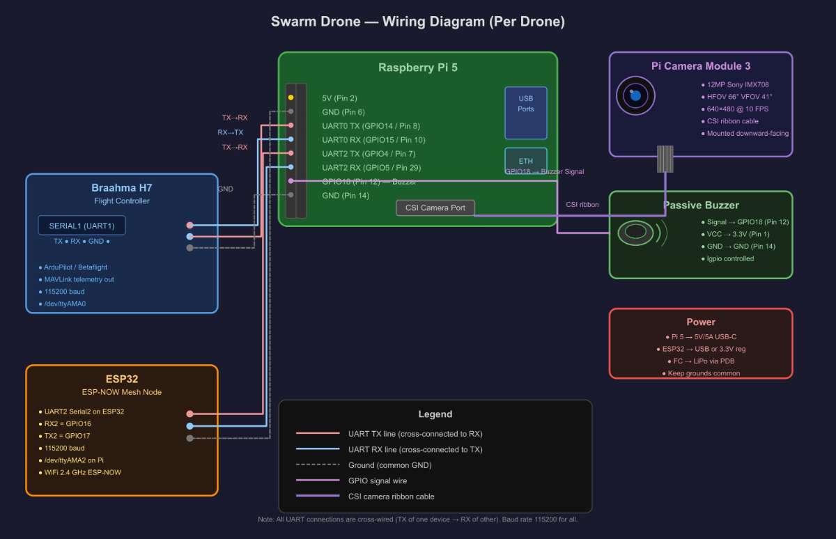
4.1 Pin Connection Table
| Raspberry Pi 5 Pin | Signal | Connects To | Device Pin |
|---|---|---|---|
| GPIO14 / Pin 8 | UART0 TX | Braahma H7 | SERIAL1 RX |
| GPIO15 / Pin 10 | UART0 RX | Braahma H7 | SERIAL1 TX |
| Pin 6 — GND | GND | Braahma H7 | GND |
| GPIO4 / Pin 7 | UART2 TX | ESP32 | GPIO16 (RX2) |
| GPIO5 / Pin 29 | UART2 RX | ESP32 | GPIO17 (TX2) |
| Pin 14 — GND | GND | ESP32 | GND |
| GPIO18 / Pin 12 | Signal | Buzzer | Signal pin |
| Pin 1 — 3.3V | VCC | Buzzer | VCC pin |
| Pin 14 — GND | GND | Buzzer | GND pin |
| CSI port | Ribbon | Pi Camera M3 | CSI connector |
4.2 Enabling UART on Raspberry Pi OS
Add the following lines to /boot/firmware/config.txt, then reboot:
   enable_uart=1          # enables UART0 on GPIO14/15
  dtoverlay=uart2        # enables UART2 on GPIO4/5
  dtoverlay=disable-bt   # frees UART0 from Bluetooth
5. Software Architecture
The codebase is split into eight Python files with a single clear responsibility each. All files share a common config (config.py) and utility library (common.py).
| File | Runs On | Responsibility |
|---|---|---|
| config.py | All drones | Single source of truth for every constant — altitudes, speeds, timeouts, pins, file paths. |
| common.py | All drones | SharedState thread bus, GPS math, MAVLink velocity / yaw helpers, buzzer driver. |
| leader.py | Leader Pi | 7-phase mission sequencer, gesture trigger, mine CSV aggregator. |
| follower.py | Follower Pi ×3 | Formation flight, command parser, MineDetector thread lifecycle. |
| gesture.py | Leader Pi | Launches camera pipeline subprocess, receives UDP result, returns snapped angle. |
| camera_sender.py | Leader Pi | Captures 640×480 JPEG frames at 10 FPS, writes to stdout as length-prefixed packets. |
| gesture_detector.py | Leader Pi | Reads piped frames, runs MediaPipe Hands, sends POINTING or TIMEOUT via UDP :9999. |
| mine_detector.py | Follower Pi ×3 | Daemon thread: YOLO inference, pixel→GPS conversion, GPS dedup, results buffer. |
5.1 SharedState — Thread-Safe Data Bus
Both the FlightThread and CommThread in every drone share data through a single SharedState object. All reads and writes are protected by a threading.Lock. The get_snapshot() method reads multiple fields atomically in one lock acquisition — this prevents the classic GPS race condition where reading latitude and longitude in separate operations can yield mismatched values if a GPS update arrives in between.
5.2 Gesture Detection Pipeline
When the leader reaches Phase 3, it spawns two subprocesses connected by a Unix pipe:
- camera_sender.py (Python 3.13) — captures frames from Pi Camera Module 3 and writes them to stdout as [4-byte big-endian length][JPEG bytes] packets at 10 FPS.
- gesture_detector.py (Python 3.11) — reads frames from stdin, runs MediaPipe Hands, detects an open palm (all five fingers extended), and sends "POINTING:<angle>" or "TIMEOUT" as a UDP datagram to 127.0.0.1:9999.
- gesture.py — receives the UDP result, snaps the raw angle to the nearest 45° (8 compass directions), beeps the buzzer for confirmation, and returns the direction to the FlightThread.
5.3 Mine Detection (Follower Drones)
When START_MOVE is received, each follower starts a MineDetector daemon thread alongside its FlightThread. The sequence is:
- Open Pi Camera Module 3 and load YOLOv11n model (normal.pt).
- Capture frames continuously (~15–20 FPS; YOLO inference takes ~100 ms per frame on Pi 5).
- For each detected bounding box: compute pixel-centre offset from image centre, scale by metres-per-pixel (derived from altitude and camera FOV), rotate by drone heading, add to drone GPS position.
- Deduplication: if the new mine GPS is within 2 m of an existing entry, update the running average position; otherwise add a new mine record.
- On STOP_MOVE: stop capture, send all unique mines to leader as MINE messages via ESP-NOW, then send MINE_DONE.
5.4 Pixel-to-GPS Conversion
The core math converting a bounding-box pixel centre to a GPS coordinate:
  # Ground footprint at current altitude
  ground_w = 2 * altitude * tan(HFOV_rad / 2)   # metres across frame
  ground_h = 2 * altitude * tan(VFOV_rad / 2)   # metres down frame
  mpp_x   = ground_w / image_width             # metres per pixel
  mpp_y   = ground_h / image_height

  # Offset of detection from image centre (camera frame)
  u = (cx - width/2)  * mpp_x   # East (+right)
  v = -(cy - height/2) * mpp_y   # North (+forward)

  # Rotate camera frame by drone magnetic heading
  north = v * cos(heading_rad) - u * sin(heading_rad)
  east  = v * sin(heading_rad) + u * cos(heading_rad)

  # Apply offset to drone GPS position
  mine_lat = drone_lat + north / 111320.0
  mine_lon = drone_lon + east  / (111320.0 * cos(radians(drone_lat)))
6. Step-by-Step Build Guide
Step 1 — Assemble the Drone Frame
- Mount brushless motors on the four arms in X-frame order: front-left and rear-right spin CCW; front-right and rear-left spin CW.
- Solder ESCs to the power distribution board or directly to the main battery lead using XT60 connectors.
- Mount the Braahma H7 flight controller at the frame centre on anti-vibration rubber standoffs.
- Connect each ESC signal wire to FC motor outputs M1–M4.
- Mount the GPS module on a riser mast at least 5 cm above the FC to reduce magnetic interference.
Step 2 — Mount Companion Computer and Peripherals
- Secure the Raspberry Pi 5 above the FC on nylon standoffs; keep it away from ESC heat sources.
- Mount Pi Camera Module 3 facing straight down through the frame opening, rigidly fixed with no play.
- Route the CSI ribbon cable carefully — avoid sharp bends, especially near the connectors.
- Mount the ESP32 on a small prototyping PCB with UART2 header pre-soldered.
- Hot-glue the passive buzzer to the frame and run short wires to GPIO18 and GND.
Step 3 — Wire All Connections
Follow the connection table in Section 4.1 exactly. Critical reminders:
- UART0 (Pi GPIO14/15) ↔ Braahma H7 SERIAL1 — main flight-controller link.
- UART2 (Pi GPIO4/5) ↔ ESP32 Serial2 (GPIO16/17) — mesh communication link.
- All grounds must be common — tie Pi GND, FC GND, and ESP32 GND together.
- Double-check TX↔RX cross-connection before powering on.
Step 4 — Configure ArduPilot on Braahma H7
- Flash ArduCopter firmware using Mission Planner or QGroundControl via USB.
- Set SERIAL1_PROTOCOL = 2 (MAVLink 2) and SERIAL1_BAUD = 115.
- Calibrate accelerometer, compass, RC, and ESCs through Mission Planner.
- Verify 3D GPS lock and check all pre-arm conditions clear before any test.
Step 5 — Set Up Raspberry Pi OS
Flash Raspberry Pi OS 64-bit (Bookworm) to the microSD card, then run:
  sudo apt update && sudo apt upgrade -y

  # Enable camera via raspi-config
  sudo raspi-config   # Interface Options -> Camera -> Enable

  # Add to /boot/firmware/config.txt:
  #  enable_uart=1
  #  dtoverlay=uart2
  #  dtoverlay=disable-bt

  sudo reboot
Step 6 — Install Python Dependencies
  # All Pis — common packages
  pip3 install dronekit pymavlink ultralytics opencv-python lgpio

  # Leader Pi only — gesture pipeline
  # Python 3.11 for MediaPipe
  pip3.11 install mediapipe opencv-python

  # Python 3.13 for Picamera2
  pip3.13 install picamera2 opencv-python

  # Fix dronekit collections compatibility (Python 3.10+)
  # Add these 3 lines at the top of follower.py and leader.py:
  # import collections, collections.abc
  # collections.MutableMapping = collections.abc.MutableMapping
  # collections.Iterable = collections.abc.Iterable
Step 7 — Deploy Code Files
  # Leader Pi
  scp config.py common.py leader.py gesture.py \
      camera_sender.py gesture_detector.py  pi@<LEADER_IP>:~/swarm/

  # Each Follower Pi  (edit DRONE_ID = 1, 2, or 3 before copying)
  scp config.py common.py follower.py mine_detector.py normal.pt \
      pi@<FOLLOWER_IP>:~/swarm/

  # Create output directories
  mkdir -p ~/swarm/mine_reports          # on leader
  mkdir -p ~/swarm/thermal/captures      # on each follower
Step 8 — Flash ESP32 Firmware
- Flash each ESP32 with an ESP-NOW UART bridge sketch via Arduino IDE or PlatformIO.
- The firmware reads bytes arriving on Serial2 (115200 baud) and broadcasts them to all registered ESP-NOW peers; received ESP-NOW packets are forwarded back to Serial2.
- Register all four ESP32 MAC addresses as peers in the firmware before flashing.
Step 9 — Pre-Flight Checks
- Power each Pi and confirm /dev/ttyAMA0 and /dev/ttyAMA2 appear in ls /dev/ttyAMA*.
- Run mine_test.py on a follower on the bench (props off) to verify Camera + YOLO + GPS GPS coordinates are producing valid output.
- Run a bench test: start follower.py on all followers, then leader.py on leader. Without props, verify ARM, TAKEOFF, FORMATION commands flow and followers acknowledge.
- Check LiPo voltage ≥ 15.5V on each 4S pack before every flight.
Step 10 — Run the Mission
  # On each Follower Pi — start BEFORE leader
  cd ~/swarm && python3 follower.py

  # On Leader Pi
  cd ~/swarm && python3 leader.py

  # Leader waits for all three followers to report READY
  # Then prompts: 'Start mission? (y/n)'
  # Type y and press Enter
  # Swarm arms, takes off, and completes the mission fully autonomously
  # Mine CSV report saved to ~/swarm/mine_reports/ after landing
7 Sample Mine Report Output (CSV)
  mine_id, follower_id,        avg_lat,    avg_lon,  best_conf, avg_alt, sightings,   best_img
  Mine-1,      1,           23.02851234, 72.57140012, 0.87,      5.1,     14,       frame_0032_14-32-01-445.jpg
  Mine-2,      2,           23.02834512, 72.57213400, 0.72,      5.1,      8,       frame_0051_14-32-18-112.jpg
  Mine-3,      3,           23.02872100, 72.57189900, 0.91,      5.1,     21,       frame_0077_14-32-40-880.jpg
8 video