
Smart Road Anomaly and Pothole Detection System
Enhancing Road Safety Through Artificial Intelligence
- Road infrastructure plays a critical role in transportation, yet potholes and road surface anomalies continue to cause accidents, vehicle damage, increased maintenance costs, and traffic disruptions. Traditional road inspection methods rely heavily on manual surveys, which are time-consuming, labor-intensive, and often unable to provide continuous monitoring.
- The Smart Road Anomaly and Pothole Detection System aims to address this challenge by utilizing Artificial Intelligence and Edge Computing to automatically detect potholes and road anomalies in real time.
What Makes This System Different?
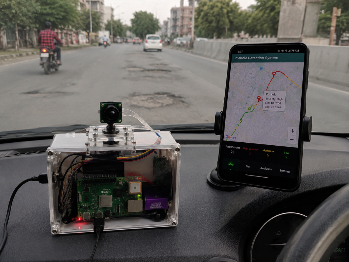
- Instead of depending on manual road inspections, our system uses a trained YOLOv8 deep learning model running on a Raspberry Pi 5. A USB webcam continuously captures road footage, and the AI model analyzes each frame to identify potholes and other road surface anomalies instantly.
- The entire detection process takes place locally on the Raspberry Pi, eliminating the need for high-performance computers or cloud-based processing. Once an anomaly is detected, the system updates a web-based dashboard that displays the detection status and monitoring results in real time.
How It Works
- The webcam captures live road images and video streams. These images are processed by the YOLOv8 model deployed on the Raspberry Pi 5. The model detects potholes and road anomalies, generates detection results, and sends the information to a web dashboard where users can monitor road conditions.
- This creates an intelligent, automated, and cost-effective road monitoring solution capable of operating continuously with minimal human intervention.
Why It Matters
- Improved Road Safety – Detects road hazards before they cause accidents.
- Reduced Vehicle Damage – Helps identify potholes that can damage vehicles and increase maintenance costs.
- Automated Monitoring – Eliminates the need for frequent manual road inspections.
- Real-Time Detection – Provides immediate identification of potholes and road anomalies.
- Cost-Effective Solution – Uses affordable hardware such as Raspberry Pi 5 and a standard USB webcam.
- Scalable Deployment – Can be installed in vehicles, roadside monitoring systems, or smart city infrastructure.
The Big Picture
Smart Road Anomaly and Pothole Detection System is more than a simple detection project. It demonstrates how Artificial Intelligence, Computer Vision, and Edge Computing can be combined to create smarter and safer transportation infrastructure. By leveraging YOLOv8, Raspberry Pi 5, and a web-based monitoring platform, the system offers a practical and scalable solution for intelligent road condition monitoring and maintenance.
Components Used :
- Raspberry Pi 5
- 32 GB Sd card
- Camera Module
- Gps Module
- Cooling Fan
Jumper Wires
Working Principle
Step 1: System Initialization
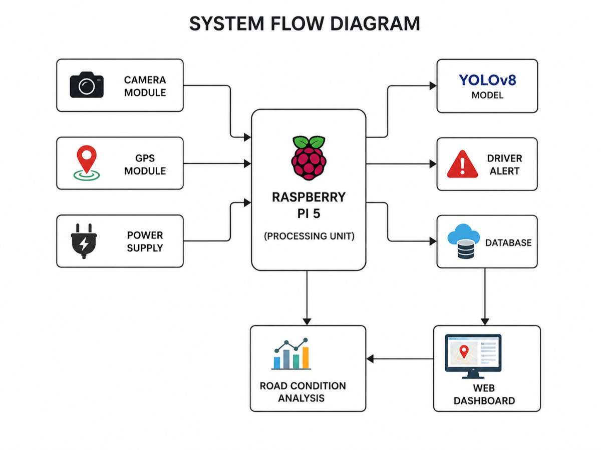
- When power is supplied, the Raspberry Pi 5 initializes all connected modules, including the Camera Module, GPS Module, Database Connection, and the YOLOv8 pothole detection model.
Step 2: Road Image Capture
- The camera continuously captures images and videos of the road while the vehicle is moving.
These images are sent to the Raspberry Pi 5 for processing.
Step 3: Pothole Detection
- The Raspberry Pi runs the trained YOLOv8 model on the captured images.
- If a pothole is detected, the system identifies its position and confidence score.
If no pothole is detected, the system continues monitoring the road.
Step 4: GPS Location Tracking
- Once a pothole is detected, the GPS module provides the current latitude and longitude coordinates.
The location information is attached to the detected pothole record.
Step 5: Driver Alert
- The system immediately generates an alert to inform the driver about the detected pothole ahead.
This helps the driver take necessary precautions and avoid vehicle damage.
Step 6: Data Storage
The Raspberry Pi stores the pothole information, including:
- Pothole Detection Status
- GPS Coordinates
- Date and Time
Detection Confidence Score
Step 7: Data Upload
- The collected data is uploaded to a cloud server or online database through an internet connection.
This enables centralized monitoring and analysis.
Step 8: Map Visualization
- The web dashboard retrieves the stored data and displays pothole locations on an interactive map.
Users can view the exact locations of potholes and monitor road conditions.
Step 9: Road Condition Analysis
The system analyzes the number of potholes in different road segments.
Based on pothole density, roads are classified as:
- Good Road Condition
- Moderate Road Damage
- Severe Road Damage
This information helps road maintenance authorities identify roads that require repair.
Block Diagram
How We Build
Hardware Implementation
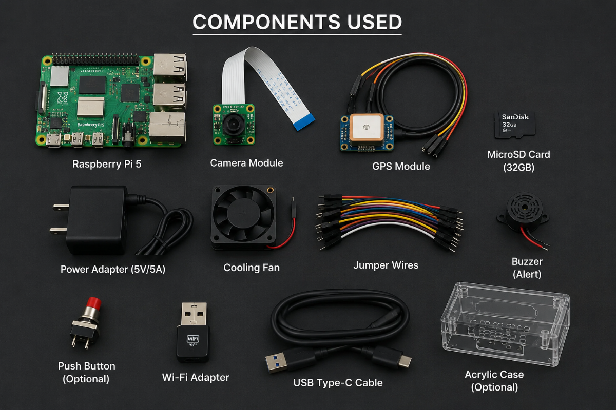
Step 1: Component Selection
The required hardware components are selected for building the pothole detection system. The main components include Raspberry Pi 5, Camera Module, GPS Module, Power Supply, MicroSD Card, Cooling Fan, and Connecting Wires.
Components
- Raspberry Pi 5
- Camera Module
- GPS Module
- Power Adapter
- MicroSD Card
- Cooling Fan
Jumper Wires
.png)
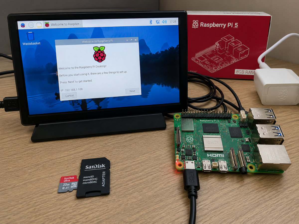
Step 2: Raspberry Pi 5 Setup
Raspberry Pi OS is installed on the MicroSD card and inserted into the Raspberry Pi 5. The board is powered using a USB-C power supply.
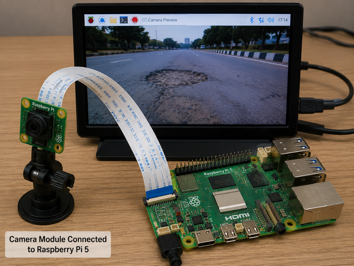
Step 3: Camera Module Connection
The camera module is connected to the Raspberry Pi using the CSI ribbon cable. The camera is mounted on the vehicle to capture road images.
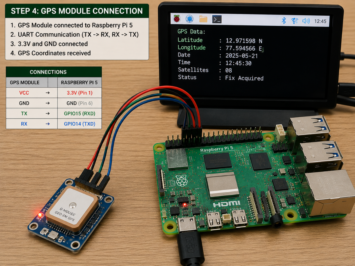
Step 4: GPS Module Connection
The GPS module is connected to the Raspberry Pi through UART communication pins. The module is configured to provide latitude and longitude coordinates.
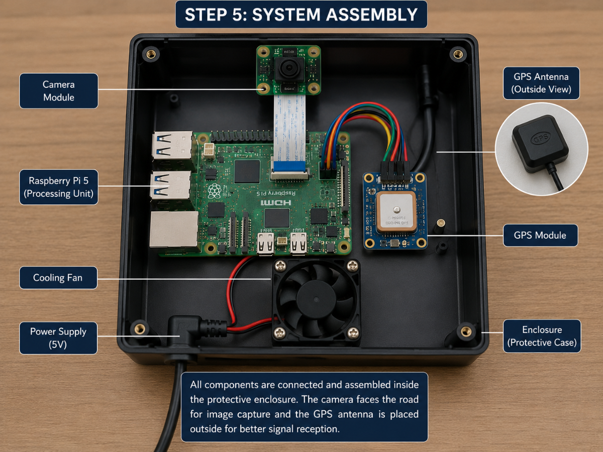
Step 5: System Assembly
All hardware components are assembled inside a protective enclosure. The camera is positioned to face the road while the GPS antenna is placed for proper satellite reception
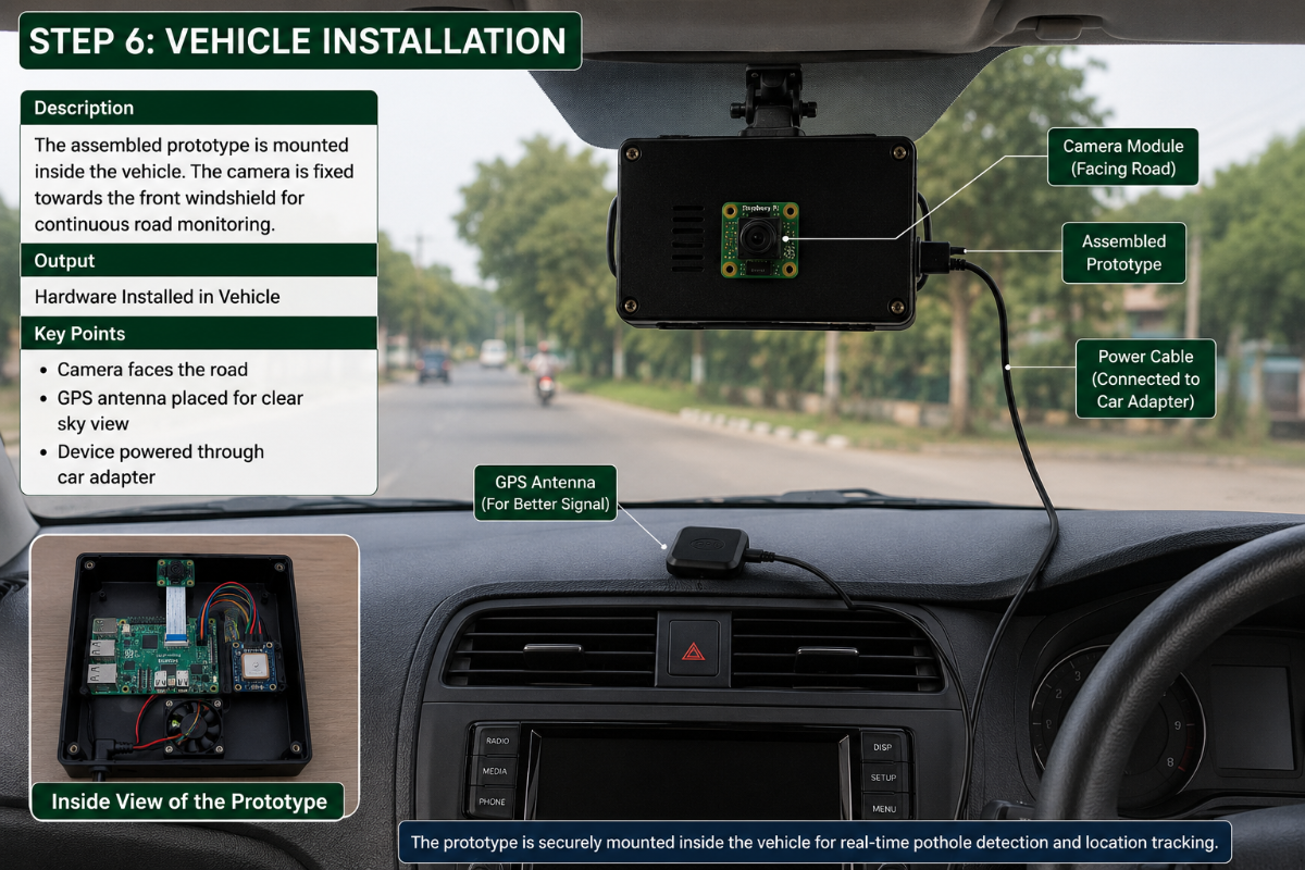
Step 6: Vehicle Installation
The assembled prototype is mounted inside the vehicle. The camera is fixed towards the front windshield for continuous road monitoring.
SOFTWARE IMPLEMENTATION
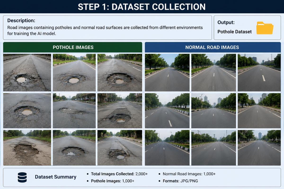
Step 1: Dataset Collection
Road images containing potholes and normal road surfaces are collected from different environments for training the AI model.
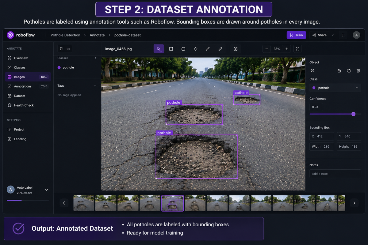
Step 2: Dataset Annotation
Potholes are labeled using annotation tools such as Roboflow. Bounding boxes are drawn around potholes in every image.
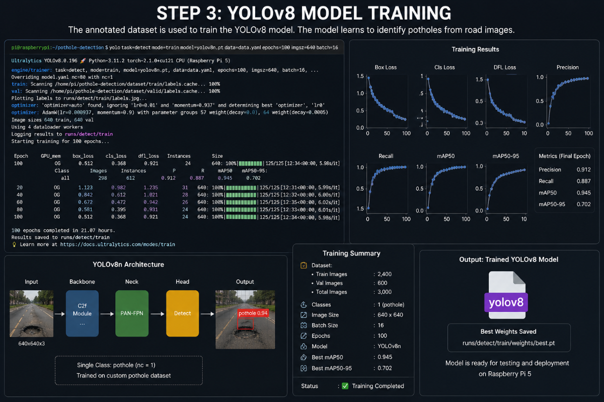
Step 3: YOLOv8 Model Training
The annotated dataset is used to train the YOLOv8 model. The model learns to identify potholes from road images.
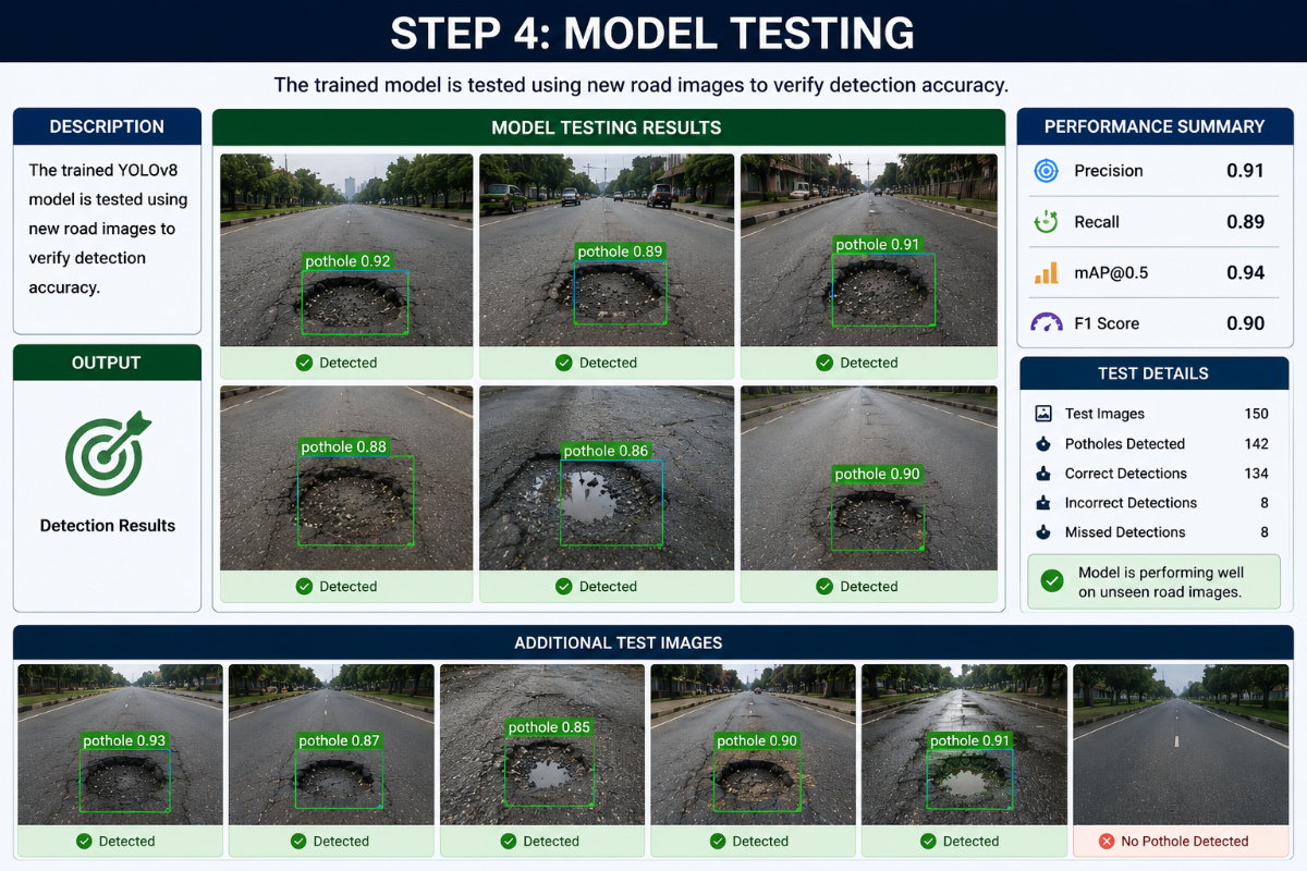
Step 4: Model Testing
The trained model is tested using new road images to verify detection accuracy.
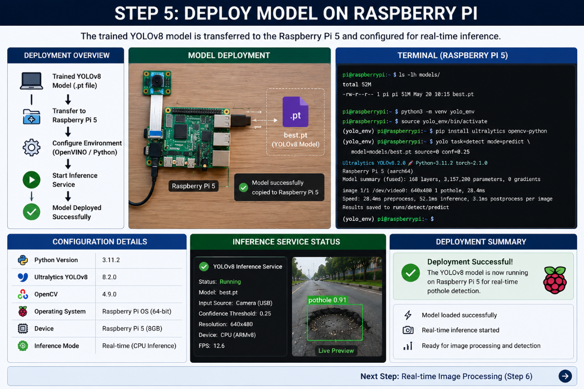
Step 5: Deploy Model on Raspberry Pi
The trained YOLOv8 model is transferred to the Raspberry Pi 5 and configured for real-time inference.
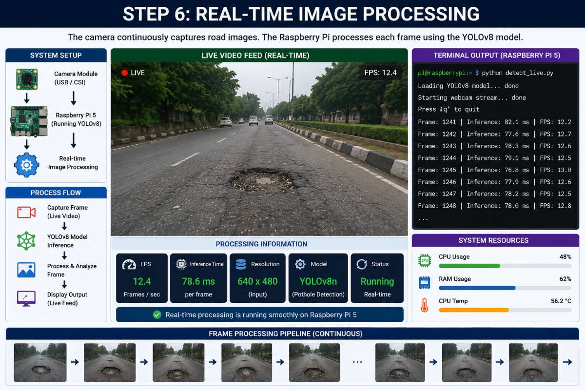
Step 6: Real-Time Image Processing
The camera continuously captures road images. The Raspberry Pi processes each frame using the YOLOv8 model.
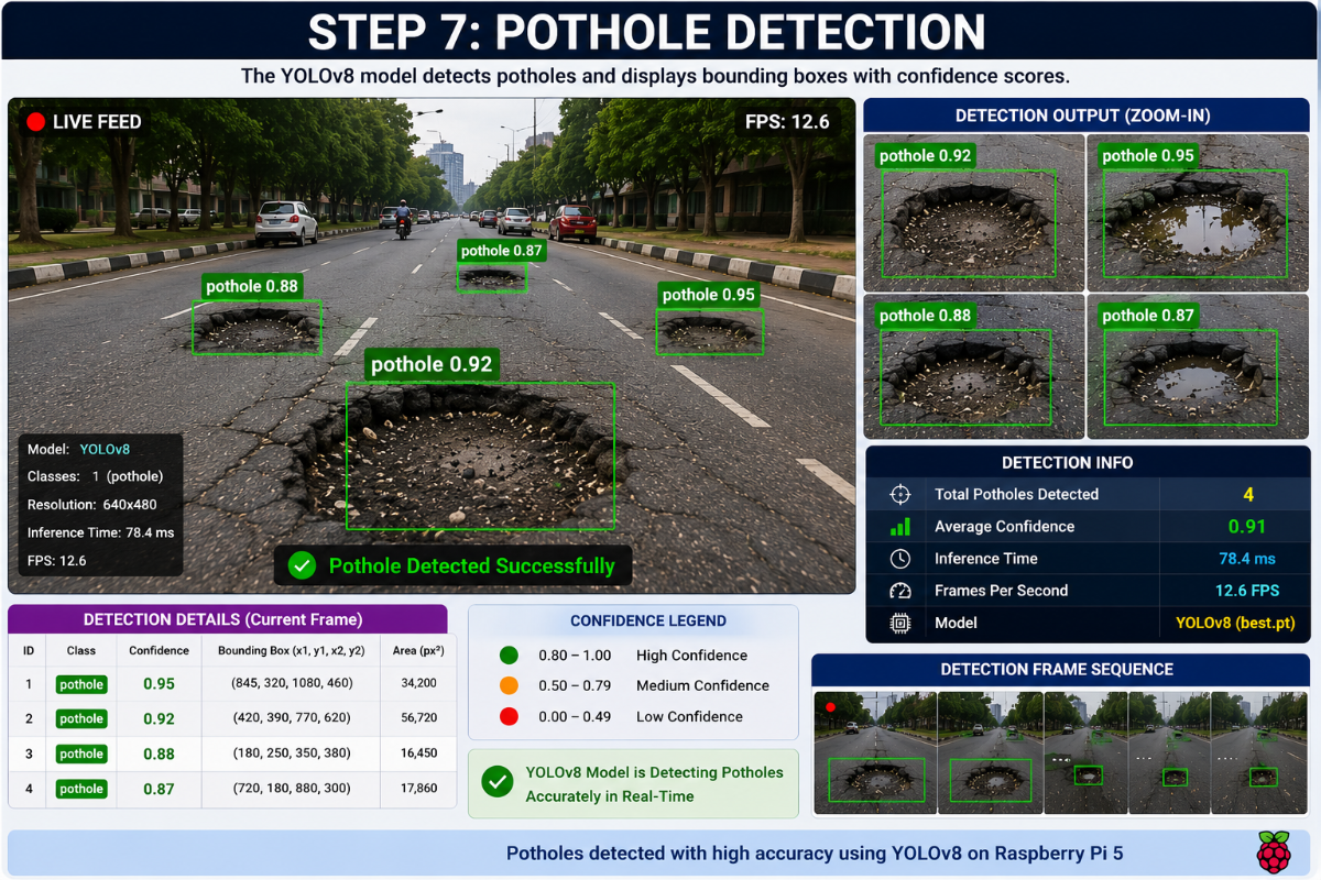
Step 7: Pothole Detection
The YOLOv8 model detects potholes and displays bounding boxes with confidence scores.
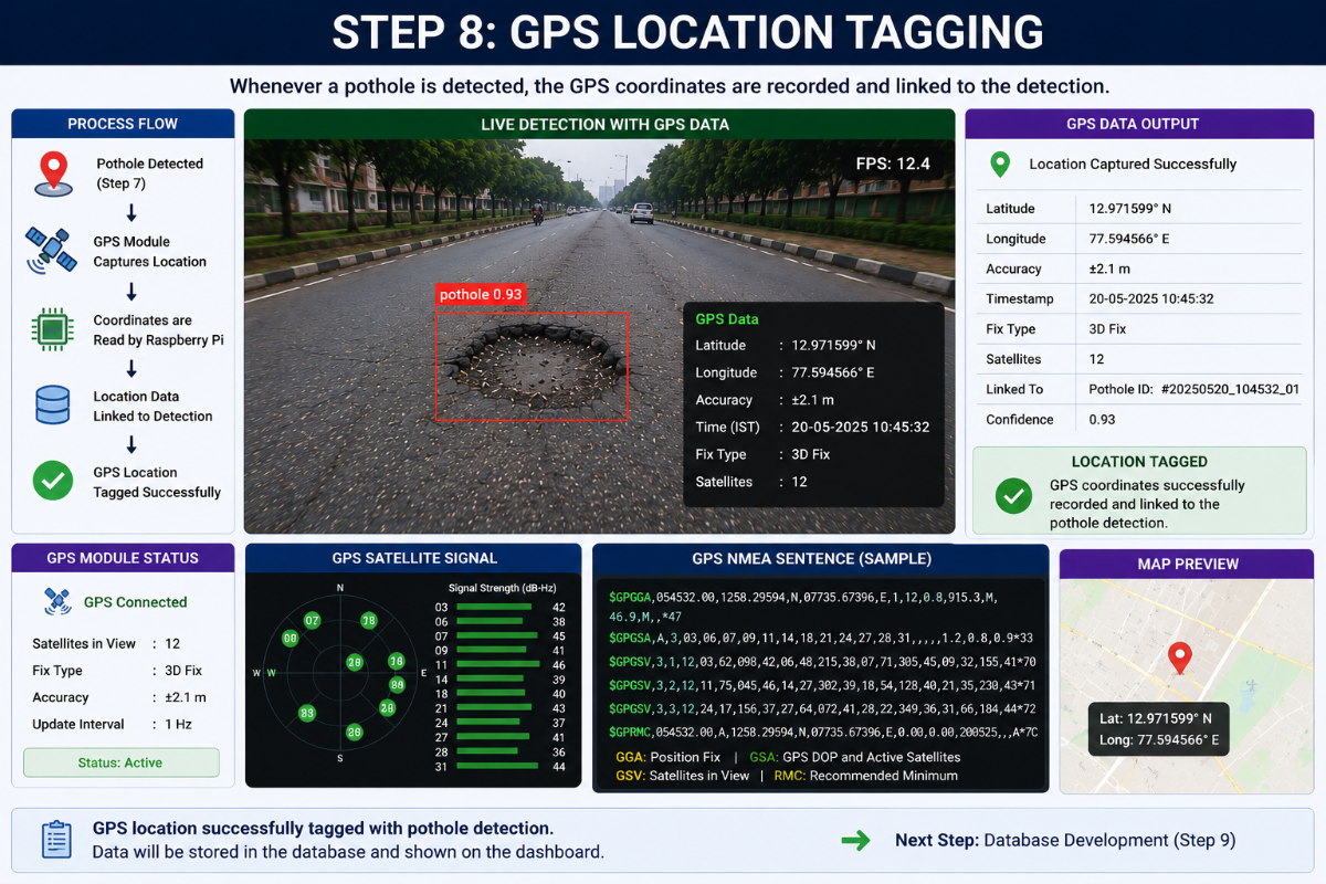
Step 8: GPS Location Tagging
Whenever a pothole is detected, the GPS coordinates are recorded and linked to the detection.
Step 9: Database Development
A database is created to store pothole information, including location, timestamp, and confidence score.
.png)
Step 10: Data Upload
The pothole information is uploaded from the Raspberry Pi to the database through an internet connection.
Step 11: Web Dashboard Development
A web dashboard is created to display pothole locations and road condition statistics.
Step 12: Map Visualization
The dashboard displays pothole locations on a digital map using GPS coordinates.
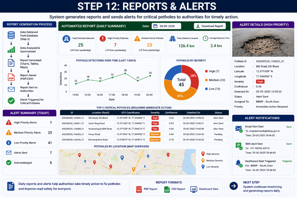
Step 13: Road Condition Analysis
The system analyzes pothole density and classifies roads as Good, Moderate, or Severe.
Step 14: Final System Testing
The complete system is tested in real-world road conditions to verify detection accuracy and system performance.
