
My project aims to provide an interesting way to play Arduboy games, by removing all the buttons.
So How Does It Work?
The directional buttons are now mercury switches meaning the player has to tilt the device to move, and the AB buttons are touch pads.
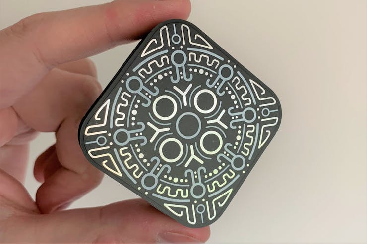
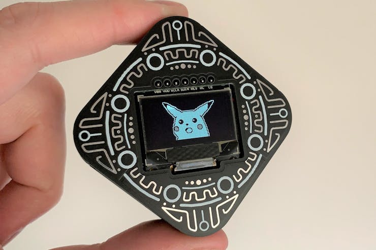
This is all packaged in a 50x50x17mm 'PCB sandwich' that doesn't require any 3D printing, screws, or glue and instead uses PCBs with Mayan-inspired patterns and standard header pins to enclose the circuitry.

Is It Actually Fun?
Yes! (I may be biased)
Here's a video of it in action, I'm playing Catacombs of the Damned:
It's hard to film since the device doesn't stay in one place. Obviously the controls are less precise than simply clicking a button, but they provide a different way of interacting with the Arduboy library of games. The sensitivity of the motion controls can be adjusted by changing the angles of the mercury switches.
Okay, How Do I Make One?
The first step is getting all the parts. The PCB gerbers are available below, along with all the Eagle PCB files you'd need to modify everything/anything.

You'll also need double-sided tape, kapton tape, and some single-core 24AWG wire
Solder the SMD Male Headers to the Back PCB. Soldering a pad at one end first then lining the header up and soldering the pad at the other end will make it easy to align.

The back PCB
Solder the SMD Female Headers to the Front PCB using the same method.

The front PCB
Solder the AT42QT1070 to the Core PCB. Make sure you have it the right way round, there is a small dot on one corner. Use small amounts of solder to avoid bridging the pins. Also solder two of the 0805 10K SMD Resistors to the nearby pads.

That's the trickiest stuff finished
Before soldering the Pro Micro to the Core PCB, upload the Pikachu-Beep.ino file, you can find it below, to the Pro Micro to check that it’s not a dud.
Do not use the headers that come with the Pro Micro. Place the Pro Micro flush against the PCB and use short pieces of wire (with the insulation removed) to secure the corners.

Solder both sides
Use more short pieces of wire to solder the remaining pads. Trim them down with some flush cutters.

This method allows for a thinner project whilst ensuring a solid connection
The TP4056 Module needs to be modified to make it safe for the 350mAh LiPo Battery. The R3 resistor needs to be removed and replaced with a 10K resistor.
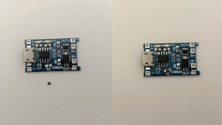
Hopefully you’ll do a better job than I did here
Use pieces of wire for the four corners of the TP4056 Module, just like you did for the Pro Micro. Solder both sides and trim the legs with flush cutters again.

Don’t worry about the B+ and B- pads for now.
Solder the Piezo Speaker to the pads shown.

Use some double-sided tape to stick the Speaker down over the circle on the top of the PCB. Make sure it doesn’t touch any of the pins or cross the holes along the edge.
If you uploaded the Pikachu-Beep sketch, you can connect the Pro Micro to power and then tap the B and A pads with your finger to check that everything is working so far. You should hear a beep when you touch the pads.
Solder the power switch onto the top edge. Put it in the OFF position.

<--ON OFF-->
Put Kapton tape across the back of the screen to ensure there are no unwanted shorts.

Use the Front PCB to hold the screen in place.

Solder the screen’s pins to the Core PCB. I suggest doing just one pin first and then checking the screen is where it’s supposed to be.
Trim all of the screens' legs on the bottom once they’re all soldered (do not solder or trim the Front PCB's header legs).
With the screen soldered on, you can now test it. Connect power to the Pro Micro (not the TP4056).

Solder the mercury switches into their corresponding places. The mercury switches should be able to move up and down a little. Moving the mercury switches is how you’ll adjust the sensitivity of the controls.

Trim the legs of the mercury switches with flush cutters.
You can test the controls by powering the Pro Micro again and listening for a beep when you tilt the device.
Cut two short lengths of wire as shown, these are going to connect to the Front PCB.

Solder them in place like so.

Fold the Front PCB over and thread the Male Header through the holes of the Core PCB. Bend the wires so that they are contained neatly.

With the power switch set to OFF, solder the battery to the B+ and B- pads. Positive goes to B+ and negative goes to B-.

Use some double-sided tape to stick the battery to the Back PCB.

Plug the Male Headers into the Female Headers and you’re finished!

Time to put some games on it. Turn the device off before connecting the Pro Micro to a PC.
Tilt the device up/down/left/right for directions and tap the patterns beside the screen for A (left side) and B (right side).