
For a detailed video explanation of the entire build process, watch here:
NeuroPulse: Wi-Fi Enabled Cognitive Training System for All Ages
NeuroPulse is an interactive LED-based therapy game designed to enhance reaction time, cognitive function, and hand-eye coordination. By integrating the ESP32-C6, the system offers wireless connectivity via esp-now protocol and improved performance. Users respond to random LED patterns, while the system provides real-time scoring and adjustable difficulty levels to keep them engaged. This compact, scalable, and IoT-ready solution is ideal for healthcare, education, and personal wellness applications.
MyLists | DigiKey - NeuroPulse
Components for Main Board
- 1x ESP32-C6-DEVKITC-1-N8
- 8x 74HC595 module
- 8x 74HC595IC
- 1x 7805
- 120x RGB led common cathode
- 20meters AWG 28 single lead wire
- 10meters per each AWG 26 wire (red, blue, white, yellow, black)
- 2x zero PCB
- 1x 16X2_I2C display
- 1x 12VDC/2A power supply
- 2x M3 X 25mm Female to Female Brass Hex
- 4x M3x20mm Male to Female Brass Hex
- 8x M3x10mm Screws
- 8x8 feet foam sheet
Components for striker
- 1x ESP32 Mini
- 1x joystick module
- 1x color sensor (TCS34725 )
- 1x vibrator
- 1x buzzer
- 1x li-po battery (3.3VDC/ 350mAh)
- 1x charger module (TP4056)
- 1x pvc endcap
- 1 role dual side tape
Making:
Step 1 – Sensor and Input Testing
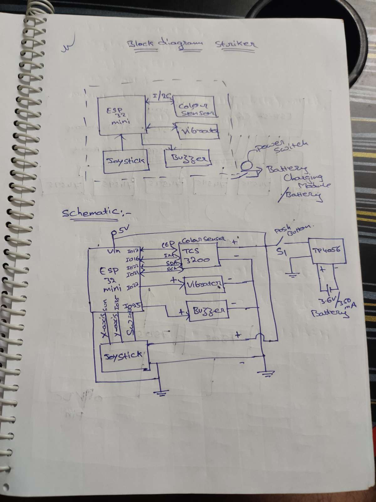
I connected the TCS34725 color sensor to the ESP32 Mini using the I2C interface, which requires only two pins—IO22 for SDA (data) and IO21 for SCL (clock). I2C is a simple 2-wire communication protocol that allows multiple sensors to share the same bus, saving GPIO pins and enabling reliable bi-directional data transfer. The color sensor’s INT pin is connected to GPIO16, and its onboard white LED control pin is connected to GPIO17. For user input, I connected the joystick’s X-axis to GPIO34 and Y-axis to GPIO35, both as analog inputs, while the joystick switch is connected as a digital input to GPIO33. For output functions, the vibration motor is connected to GPIO27 and the buzzer to GPIO25. All these values—joystick X, joystick Y, switch status, and color sensor output—are combined into a single packet in the format “<x-value>,<y-value>,<sw>,<colour>” for further processing or wireless transmission.
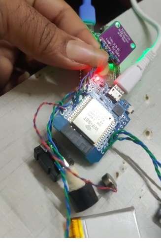
I call this module the Striker in the game, and it operates wirelessly using ESP-NOW for fast and reliable communication. For the power supply, I am using a Li-ion battery (3.3 V / 350 mAh), which is charged through a TP4056 charging module. I added a power control switch to turn the entire Striker module ON and OFF. Using the circuit diagram below, I connected the above circuitry to complete the Striker module assembly.
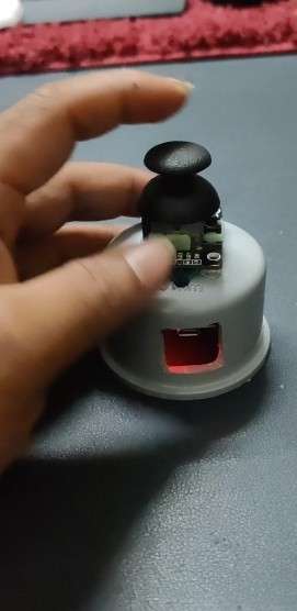
for assemble case, I used PVC pipe endcaps and made a side hole using a drill to access the USB port. After preparing the enclosure, I placed all the circuitry inside the endcap and fixed it securely using double-sided tape and a glue gun. Once the assembly was completed, it gave a clean, compact, and sturdy finish.
Now coming to the programming section—using the Arduino IDE, I flashed the program to the ESP32. When the board is connected, the correct ESP32 board model is selected automatically or from the board manager. In the program logic, the ESP32 continuously broadcasts data via ESP-NOW, and the receiving module listens using its predefined MAC address. Once the data is received, it processes the information and executes the corresponding game logic. Here, I first form a data packet and print it on the Serial Monitor for testing before sending it wirelessly.
Step 2 – Preparing the Foam Sheet Base Board
I used a 5 mm thick foam sheet of size 3 × 2 feet. After marking the LED placement layout, I designed two separate LED matrix sections: one 8×8 matrix and one 7×7 matrix. For clear identification, I marked the 7×7 matrix in blue and the 8×8 matrix in red, making the layout easy to follow during assembly and wiring.
After marking
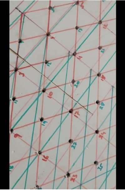
Step 3 – Drilling Holes
I made holes in the foam sheet according to the marked matrix layout. Since I planned to fit 5 mm LEDs, I used a 6 mm drill bit to create slightly larger holes, allowing the LEDs to fit easily and securely without damaging the foam.
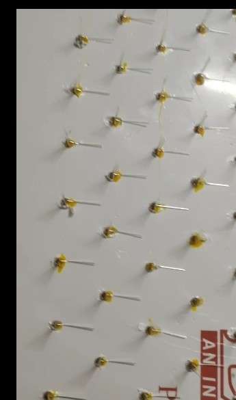
Step 4 – Inserting RGB LEDs
I inserted all the RGB LEDs into the holes and applied glue to hold them firmly in place. After completing the placement, I left the sheet overnight to allow the glue to dry completely, ensuring the LEDs were fixed securely.
Step 5 – LED Wiring Preparation
I bent the LED legs using a tweezer and nose plier, making sure to maintain proper distance between each leg while bending so they wouldn’t touch or short. All anodes were bent to one side and all cathodes to the opposite side, making it easier to form the matrix. Using AWG28 single-standed wire, I soldered each LED and grouped the color pins separately. All red pins of the 7×7 matrix were connected together, and all red pins of the 8×8 matrix were connected together separately. The same method was followed for the green and blue pins, completing the RGB matrix wiring in both sections.
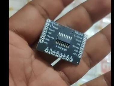
Step 6 – Adding Shift Registers
I placed the shift registers for both the anode side and the cathode side. Here I used 74HC595 shift registers, each having 8 output pins, which allowed me to connect each LED line directly to the corresponding shift-register pin. For the 8×8 matrix, I used one shift register for red, one for green, and one for blue—a total of 3 shift registers. Similarly, for the 7×7 matrix, I again used 3 shift registers (one for each color).
This makes the total on the LED (anode) side = 6 shift registers (3 for 8×8 + 3 for 7×7).
On the cathode side, I used 1 shift register for the 8×8 matrix and 1 shift register for the 7×7 matrix, adding 2 more modules.
So in total, I connected 8 shift-register modules (6 on the anode/color side and 2 on the cathode side) to complete the full LED matrix wiring.
Step 7 – Signal Pin Setup
I connected as per circuit diagram:
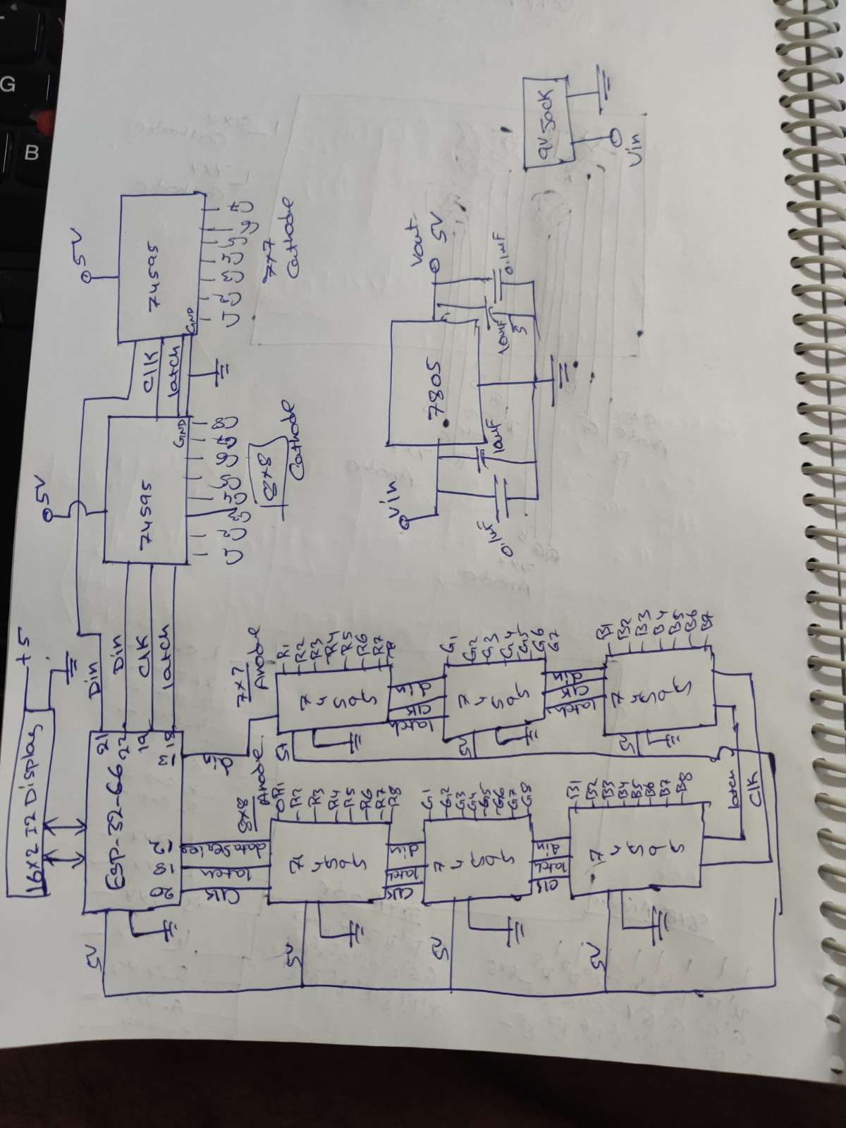
I connected everything as per the circuit diagram. All latch pins from both the anode-side and cathode-side shift registers were tied together and connected to GPIO18. The serial data lines were kept separate for each matrix and each section: GPIO12 for the 8×8 anode side, GPIO13 for the 7×7 anode side, GPIO22 for the 8×8 cathode side, and GPIO21 for the 7×7 cathode side. I also used a common clock line for all anode-side shift registers connected to GPIO20, and another common clock line for all cathode-side shift registers connected to GPIO19. This setup ensures proper shifting, synchronized latching, and independent control of both the 7×7 and 8×8 matrices.
Step 8 – Controller and Display Connection
I connected the ESP32-C6 to all the shift registers and also attached the 16×2 LCD using the I2C interface. The LCD was connected to the ESP32-C6’s standard I2C pins, with GPIO6 as SDA and GPIO7 as SCL, allowing the display to show output while the microcontroller controls both LED matrices through the shift registers.
Step 9 – LED Test Code
I wrote a test code to randomly blink the LEDs on the matrix to verify the hardware functionality. Using the Arduino IDE, I flashed the code to the ESP32-C6. In this test, the LEDs blink in different colors, but only one color is activated at a time. All LEDs are turned ON one after another to ensure every LED and color channel is working properly.
Step 10 – Wireless Communication
I established wireless communication between the two ESP32 boards (master and striker) using ESP-NOW and verified successful data transfer. Before building the full code, I first tested communication between both boards. To do this, I needed the MAC ID of the slave board (ESP32-C6 Mini), so I wrote a MAC ID scanner program to read and display the device’s MAC address. After getting the MAC ID, I added it to the master (Striker) ESP32 code. I opened two parallel tabs in the Arduino IDE and monitored both Serial Monitors. Once the ESP-NOW connection was established, the master showed “send successful” and the slave showed “receive successful,” confirming proper wireless communication.
Step 11 – Game Logic & Scoring
This program runs on an ESP32-C6 slave unit that receives color and button data from a master device using ESP-NOW, displays game information on a 16×2 I2C LCD, and controls two RGB LED matrices (8×8 and 7×7) using shift registers. After initializing the LCD, WiFi (for ESP-NOW), and all shift-register pins, the code listens for messages from the master; whenever data is received, it extracts the color and joystick button status, updates scores for Red/Green/Blue, checks whether the player should level up, and adjusts LED blink speed based on the level. It also monitors master connection status using a timeout—resetting the game when connected, and showing final results when disconnected. The main loop continuously updates the LCD with level, timer, button status, and RGB scores, while the LED matrices randomly blink single RGB pixels using shift-register shifting (anode RGB + cathode column select). Overall, this code combines ESP-NOW wireless input, LCD feedback, score/level system, and RGB matrix visuals for your NeuroPulse reaction-training game.
Future Scope:
This project has enormous expansion potential, as the same hardware can support 100+ new game modes through software updates alone, without changing any electronic components. The main board can also be enhanced by replacing the LCD with smartphone connectivity, where all game data, timers, scores, and live LED patterns are streamed directly to a mobile app using BLE, Wi-Fi, or ESP-NOW–to-BLE bridging, providing a richer and more interactive user experience. On the striker side, the same module can be upgraded to function as a full wireless joystick by enabling BLE communication in the firmware, allowing players to switch between multiple game types simply by updating the main board software. From the mechanical perspective, the entire system can be transformed into a professional product by designing custom PCBs for both the striker and the main board, along with developing a strong and commercially appealing enclosure, making the device reliable, user-friendly, and ready for real-world deployment or commercial production.
Applications
- Cognitive Rehabilitation: Helps patients recovering from TBI, stroke, neurological disorders, or delayed cognitive response.
- Physiotherapy & Reaction Training: Improves motor control, reflex speed, and coordination using visual–motor stimuli.
- Educational Tools: Useful in schools and skill-development centers to improve attention, focus, and learning through gamified activities.
- Esports & Gaming Training: Enhances hand–eye coordination, response timing, and spatial awareness for gamers.
- Fitness & Sports Training: Builds agility, reaction accuracy, and timing for athletes.
- Therapeutic Stress Relief: LED patterns combined with task engagement reduce stress and improve concentration.
Advantages
- Fully Wireless Operation (ESP-NOW): No latency, low power, and high-speed communication for smooth gameplay.
- Highly Scalable: Hardware remains the same—100+ games can be added with software updates.
- Portable & Compact: Lightweight design makes it usable at home, clinics, schools, and training centers.
- Improves Multiple Skills: Enhances reaction time, memory, focus, visual tracking, and hand–eye coordination.
- Customizable Difficulty Levels: Makes the system suitable for beginners to advanced users.
- IoT Ready: Can transmit data to mobile apps for analytics, progress tracking, and remote monitoring.
- Therapy + Entertainment: Acts as both a rehabilitation tool and a fun, interactive game system.
Disadvantages
- Dependent on User's Physical Ability: Users with severe motor disabilities may find difficulty using the joystick or reacting quickly.
- Requires Battery Management: Striker module needs regular charging (Li-ion + TP4056).
- Ambient Light Can Affect Sensor Reading: Color sensor performance may reduce in bright or reflective environments.
- Learning Curve: Some users may take time to understand patterns or game rules, especially elderly patients.
- Maintenance: LED matrix wiring and shift registers need careful assembly to avoid loose connections.
Suitable Age Group
- Children (6+ years):
Improves learning, attention, focus, and reaction speed — safe and engaging for kids. - Teenagers & Adults (13–50 years):
Great for skill training, gaming, memory enhancement, and fast-reflex activities. - Elderly (50+ years):
Helps maintain cognitive activity, prevents decline, and offers light physical engagement. - Patients Under Rehabilitation (All ages, supervised):
Suitable for TBI, stroke, neuro-therapy, and physiotherapy sessions.