

QGBT4.0
QGBT4.0 (low voltage framework 4.0) came with the aim of helping people spend more consciously, this is becoming more and more common to profit by saving and this is very easy to do today.
How QGBT works.
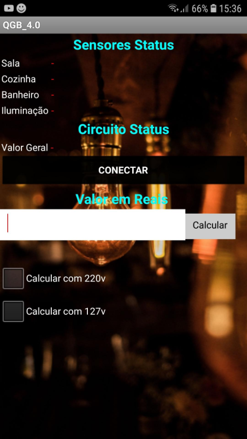
the framework has certain modern concepts, which are addressed, among them, the IOT, HOUSE AUTOMATED, and INDUSTRY 4.0. the board has a mobile application that reads from a server site (ThingSpeak), the server site works with information that the sensors send to the board. This mobile application will show the following information, the ampere of each separate room, the general value of ampere consumption in the whole house, and the application screen has a text box that serves to convert the measured values into the types of expenses.
Development
the development of this project is simple and easy to understand.
- Make sure the necessary parts and materials were used to create this project: circuit breakers, general voltage low voltage materials, Arduino, esp8266 generic module, sockets, lamps, and buttons.
- programming: Arduino and esp8266 must be programmed in the Arduino IDE, once installed, make some configurations in the IDE so that the code does not result in an error in the esp8266 and Arduino, or in the compilation: to program the Arduino, it is necessary to add an "emonlib" library that works to convert readings to amperage to learn more about how the Arduino handles reading data, click here image.
.png)
To include this library, click on the library manager that will open a library and a search window, search for emonlib, and install. The next step is to configure the IDE for esp8266, enter the Files tab and, in Preferences, find the URL for the additional text box and paste the following.
http://arduino.esp8266.com/stable/package_esp8266com_index.json.
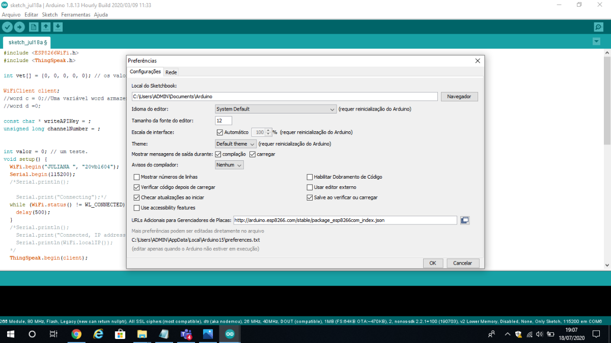
then go back to the library manager and put on ThingSpeak (I'll explain later). and prepare your IDE ready to load the code. recommend before sending the code to esp8266 watch this video
he teaches how to work with esp8266.
ESP code
#include <ESP8266WiFi.h>
#include <ThingSpeak.h>

int vet[] = {0, 0, 0, 0, 0}; // os valores.

WiFiClient client;
//word c = 0;//Uma variável word armazena um número sem sinal de ao menos 16 bits, de 0 A 65535.
//word d =0;

const char * writeAPIKey = ;
unsigned long channelNumber = ;


int valor = 0; // um teste.
void setup() {
  WiFi.begin("JULIANA ", "20vb1604");
  Serial.begin(115200);
  /*Serial.println();

    Serial.print("Connecting");*/
  while (WiFi.status() != WL_CONNECTED) {
    delay(500);
  }
  /*Serial.println();
    Serial.print("Connected, IP address: ");
    Serial.println(WiFi.localIP());
  */
  ThingSpeak.begin(client);


}
void loop() {
  for (int x = 0; x < 5; x++) {
    if (Serial.available() > 0) {
      delay(200);
      word c = Serial.read();
      delay(100);
      vet[x] = c;

    }
  }

    //valor++;

    ThingSpeak.writeFields (channelNumber, writeAPIKey);
    delay(100);

      ThingSpeak.setField(1, vet[0]);
      delay(100);


      ThingSpeak.setField(2, vet[1]);
      delay(100);


      ThingSpeak.setField(3, vet[2]);
      delay(100);

      ThingSpeak.setField(4, vet[3]);
      delay(100);

      ThingSpeak.setField(5, vet[4]);
      delay(100);


}
Arduino code
#include "EmonLib.h"

float banheiro = A1;
float cozinha = A2;
float ilumina = A3;
float total = A4;
float sala = A0;

EnergyMonitor SCT013;
EnergyMonitor SCT012;
EnergyMonitor SCT010;
EnergyMonitor SCT011;
EnergyMonitor SCT01;

void setup() {
  Serial.begin(115200);
  SCT013.current (sala, 60.700);
  SCT012.current (total, 60.700);
  SCT010.current (cozinha, 60.700);
  SCT011.current (banheiro, 60.700);
  SCT01.current (ilumina, 60.700);
}

void loop() {

  int total = SCT012.calcIrms(1480);
  delay(10);


  int cozinha = SCT010.calcIrms(1480);
  delay(10);


  int sala = SCT013.calcIrms(1480);
  delay(10);


  int banheiro = SCT011.calcIrms(1480);
  delay(10);


  int ilumina = SCT01.calcIrms(1480);
  delay(10);


  for (int c = 1; c <= 5; c++) {

    if (c == 1) {
      Serial.write(sala);
      delay(300);
    }
    if (c == 2) {
      Serial.write(total);
      delay(300);
    }
    if (c == 3) {
      Serial.write(cozinha);
      delay(300);
    }

    if (c == 4) {
      Serial.write(banheiro);
      delay(300);
    }

    if (c == 5) {
      Serial.write(ilumina);
      delay(300);
    }

  }


}
3. the fourth step is to register on the ThingSpeak website, which will serve as our server, and program the mobile application with the appinventor. To start subscribing to the ThingSpeak website, click on the new channel, create a channel, and select five fields.
.png)
After creating your channel, you need to access the API key configuration and copy the read link from the channel ID field, API key, and read the field into a channel. with your channel ID and the API key, you put in esp8266 programming. And the link will be used in the inventor application.
.png)
to see each step click here.
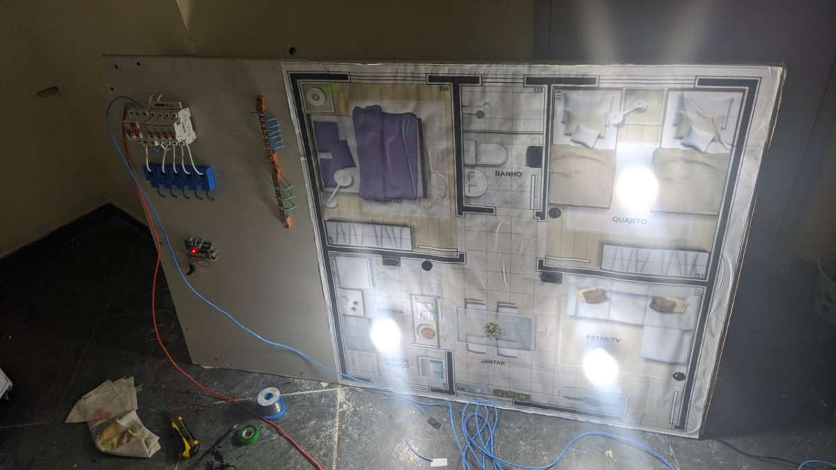
4. Now, just configure the board with the circuit breakers, sockets, lamps, and buttons. be careful with the Arduino pins. the Arduino and the esp8266 circuit are interconnected between the RX, tx pins, the esp8266 VCC pin must be connected to 3.3 volts, it has a ch_pd pin that must be connected in high mode for the board to be put into normal operation. The Arduino will have the following pins A0, A1, A3, A4, A5 in operation, which will take the current readings from the sensor. Circuit breakers will be connected normally according to NBR standards.
.png)
finally finishes testing