


PROBLEM STATEMENT
Our problem statement is to help the paralyzed to move their wheel chair without others assistance. To transform our idea into actions we've started building our prototype.
TEAM'S APPROACH:
Our team’s main aim to solve the problem of the mobility of the paralyzed people by controlling the speed and direction of the wheelchair by the head movements that help in moving from one place to another place easily with a negligible amount of difficulty.
We could design an electronic wheelchair that would move according to the instructions of the patient by his head movements and that would be completely wireless transmission with good accuracy.
This prototype solves the problem of mobility of paralyzed people by controlling speed and direction of wheel chair. The head movements decide the speed and direction of wheel chair with almost negligible amount of difficulty
Components
- STM 32
- NRF 24L01
- GYRO SENSOR(MPU6050)
- MOTOR DRIVER(L298N)
- CENTER SHAFT MOTORS
STEP 1
Install aurdino ide in your pc and also install respected libraries like nRF24L01,SPI,RF24-STM_config.
STEP 2
Connect the gyro sensor and a NRF module which (will act as the transmitter) to STM32(micro controller) with which we can be able to know the information of movement
Transmitter Connection
Receiver Connection
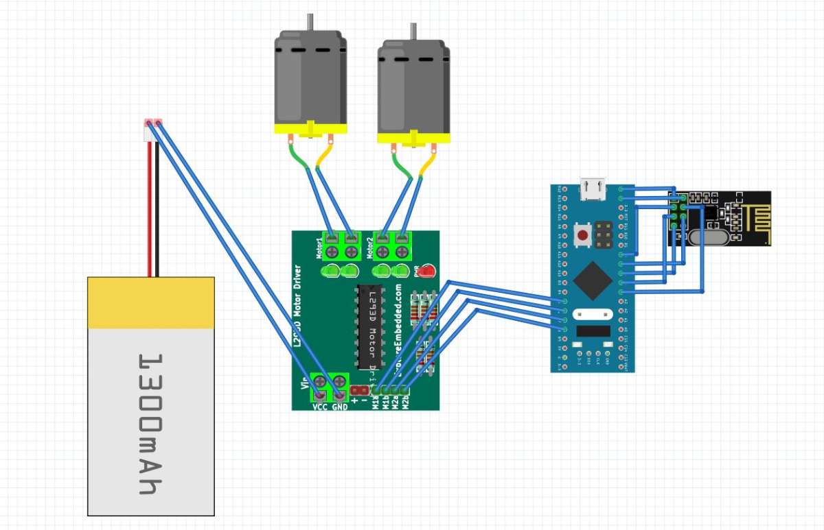
STEP 3
Also connect NRF module to the micro controller which will act as transceiver for the project.
STEP 4
Then connect the motor driver to the motors and also to the micro controller .
STEP 5
Now power the motor driver with external battery or any power bank.
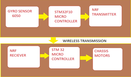
WORKING
The Automatic Wheel Chair it's movement is depends upon the change in degrees of freedom detected by the gyro sensor (X,Y,Z axis) . The information is transferred by the nrf module attached to the gyro sensor and received by the nrf module attached to the wheel chair. This whole information transferring occurs in SPI communication protocol .
The movements of wheels of the wheel chair is controlled by the motor driver , which can be altered by the motion of the user's head