Conveyor with PWM Speed and Item Counting
Helping Small Businesses Improve Production Efficiency
Many micro, small, and medium-sized enterprises (MSMEs) still rely on manual methods to transport and count products during production and packaging. As production volume increases, these repetitive tasks become more time-consuming, labor-intensive, and susceptible to human error, reducing operational efficiency and inventory accuracy.
Although industrial conveyor systems with automated counting capabilities are widely available, their cost and implementation complexity often make them inaccessible to small businesses and educational institutions.
As a solution, this project implements a low-cost automated conveyor system that helps improve production efficiency by automating the item counting process while remaining simple, affordable, and easy to build. The prototype demonstrates how practical automation can improve counting accuracy, reduce human error, and support small-scale manufacturing as well as educational applications.
What Makes This Conveyor Project Different?
Rather than functioning as a simple miniature conveyor, this prototype incorporates several automation features commonly found in industrial conveyor systems. Operators can manually adjust the conveyor speed using PWM control, change its direction, and rely on an integrated laser–LDR sensing system to count every passing item automatically.
The counting result is displayed instantly on a 16×2 LCD, eliminating repetitive manual counting and helping reduce human error. When a counting session is complete, the counter can be cleared to zero with a dedicated reset button, allowing the system to be reused immediately.
By integrating motor control, object detection, and real-time counting into a single prototype, this project demonstrates that practical industrial automation does not always require expensive equipment. It provides an affordable, easy-to-replicate platform for students, makers, and MSMEs to explore production automation and embedded control systems.
Why It Matters
- Improves Productivity – Automates repetitive item counting during production.
- Reduces Human Error – Minimizes mistakes caused by manual counting.
- Affordable Automation – Demonstrates industrial automation using low-cost and widely available components.
- Educational Platform – Helps students and makers understand motor control, sensors, and embedded systems through hands-on implementation.
- Scalable Concept – The prototype can be expanded with IoT monitoring, quality inspection, barcode scanning, or sorting mechanisms for more advanced industrial applications.
Device Wiring
● Arduino Pro Mini (Motor Speed Control) :
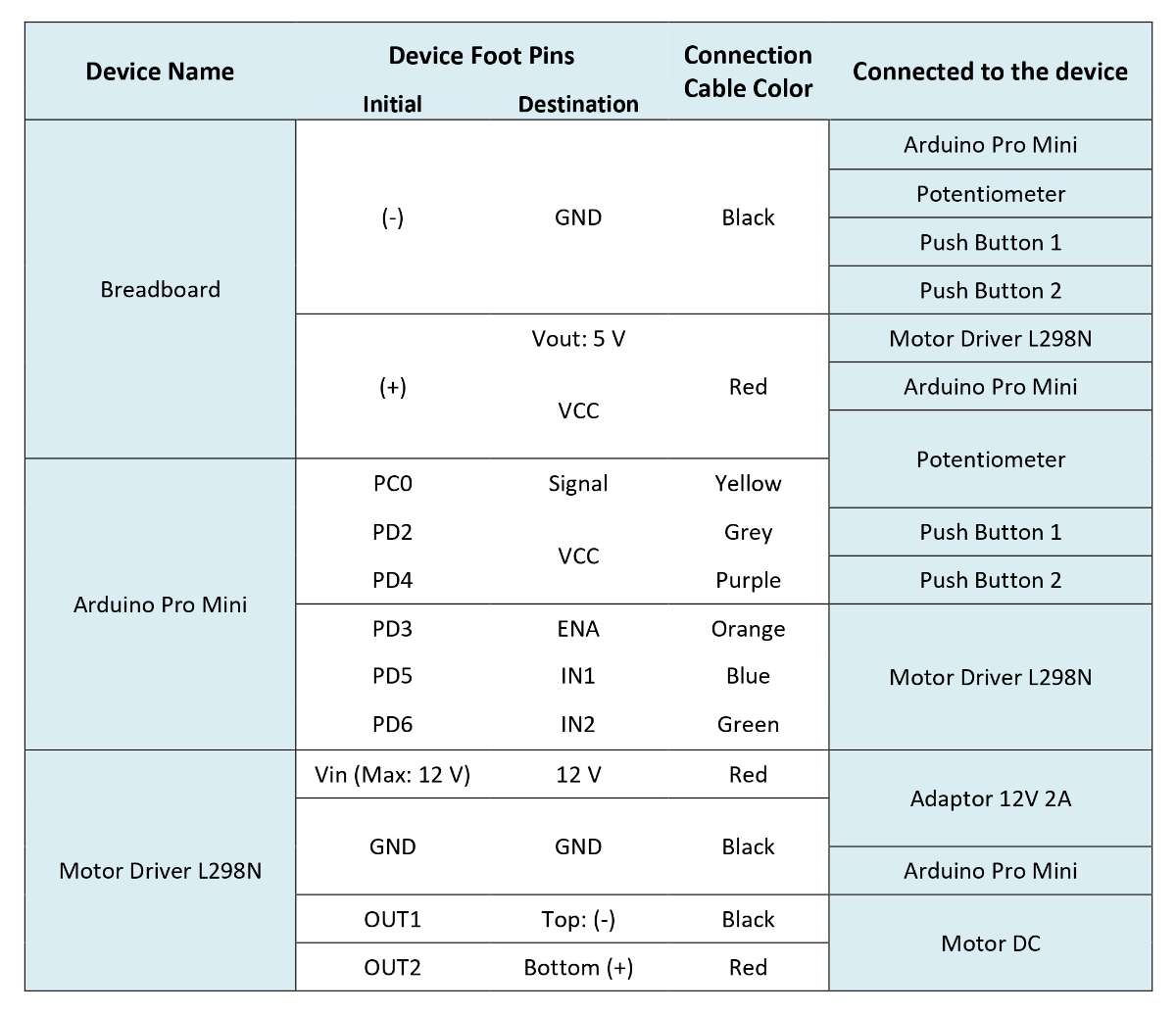
● STM8S103F3P6 (Items Counting) :
.jpg)
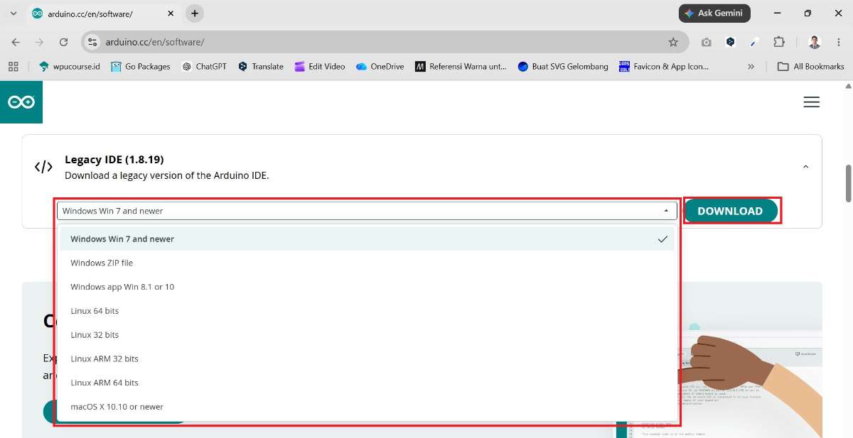
Step 1 : Download & Install Arduino IDE
Please click the following link to download the Arduino IDE :
Select Legacy IDE (1.8.19).
.jpg)
Please select the OS (Operating System) ➜ Click Download.
Open the
Downloadsfolder ➜ Selectarduino-1.8.19-windows➜ Right-click ➜ SelectRun as administrator.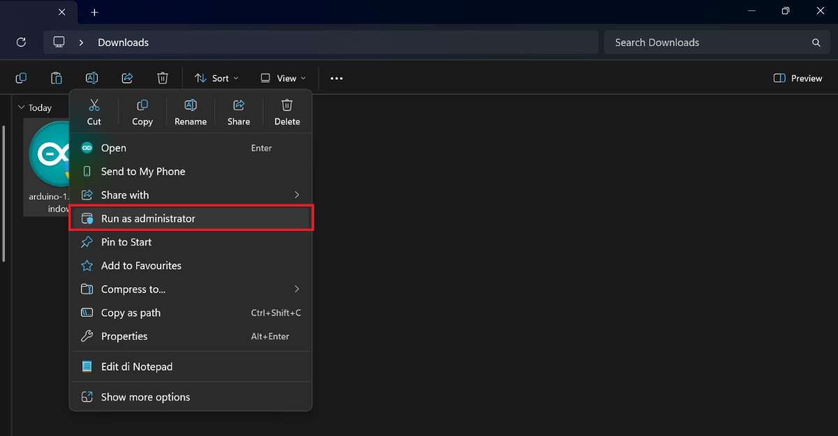
Arduino Setup: License Agreement ➜ Click
I Agree.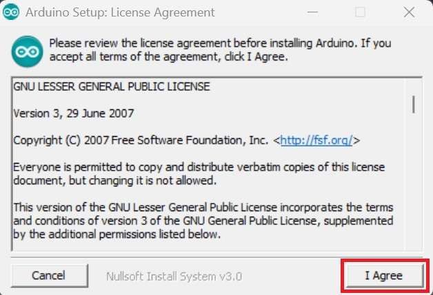
Arduino Setup: Installation Options ➜ Click
Next.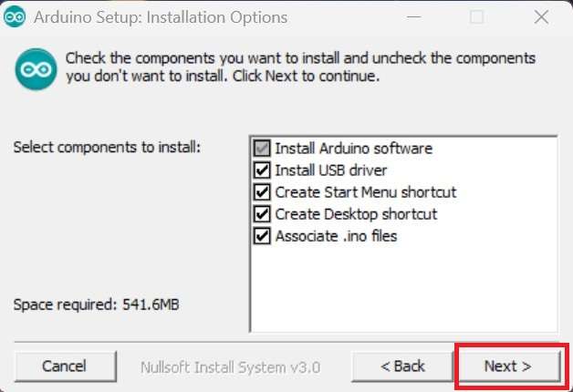
Arduino Setup: Installation Folder ➜ Click
Install.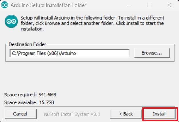
Please wait for the installation to complete.
.jpg)
- Once the installation is complete ➜ Click
Close.
Step 2 : Arduino IDE Configuration
Open the Application (.EXE) :
Arduino IDESelect
File➜Preferences.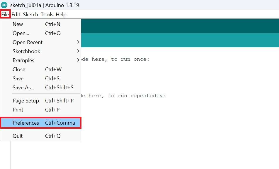
In addition to the Arduino board, you must manually fill in the
Additional Board Manager URLsfield in the Arduino IDE, as shown in the example below :https://raw.githubusercontent.com/tenbaht/sduino/master/package_sduino_stm8_index.json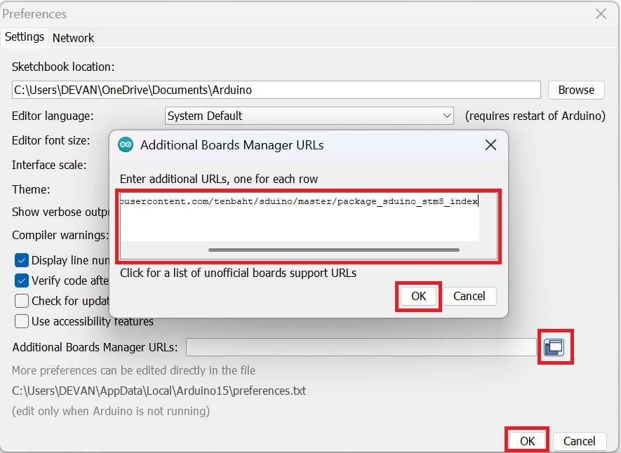
Select
Tools➜Board➜ ClickBoards Manager.Make sure the Arduino AVR board is already installed. If not, you must install it.
.jpg)
Then type
stm8➜ SelectSduino STM8 plain C core (non-C++)by Michael Mayer ➜ ClickInstall..jpg)
Wait until the installation is complete ➜ Click
Close.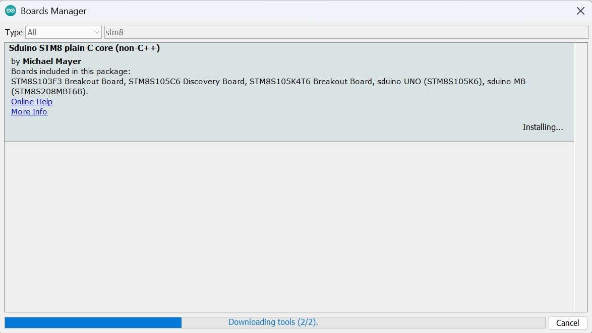
Step 3 : Download & Install PL2303 USB Driver
Please click the following link to download the PL2303 USB Driver :
Select
PL2303 Prolific DriverInstaller.zip➜ ClickDownload.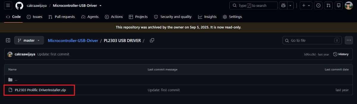
Open the
Downloadsfolder ➜ Right-click ➜ SelectExtract Here..jpg)
Open the folder containing the extracted files ➜ Select
PL2303-Prolific_DriverInstaller_v1200➜ Right-click ➜ SelectRun as administrator..jpg)
To begin the installation ➜ click
Next..jpg)
Wait until the installation is complete ➜ Click
Finish..jpg)
Step 4 : Download & Install ST-Link USB Driver
Please click the following link to download the ST-Link USB Driver :
Select
en.stsw-link009.zip➜ ClickDownload..jpg)
Open the
Downloadsfolder ➜ Right-click ➜ SelectExtract Here..jpg)
Open the folder containing the extracted files ➜ Select
dpinst_amd64➜ Right-click ➜ SelectRun as administrator..jpg)
To begin the installation ➜ click
Next..jpg)
Wait until the installation is complete ➜ Click
Finish..jpg)
Step 5 : Download & Install FTDI USB Driver
Please click the following link to download the FTDI USB Driver :
Select
CDM212364_Setup.zip➜ ClickDownload..jpg)
Open the
Downloadsfolder ➜ Right-click ➜ SelectExtract Here..jpg)
Open the folder containing the extracted files ➜ Select
CDM212364_Setup➜ Right-click ➜ SelectRun as administrator..jpg)
To begin the installation ➜ click
Extract➜Next..jpg)
.jpg)
License Agreement ➜ Make sure you have selected the option:
I accept this agreement. Then clickNext..jpg)
Wait until the installation is complete ➜ Click
Finish..jpg)
Step 6 : Download & Install CH340 USB Driver
Please click the following link to download the CH340 USB Driver :
Select
CH341SER.zip➜ ClickDownload..jpg)
Open the
Downloadsfolder ➜ Right-click ➜ SelectExtract Here..jpg)
Open the folder containing the extracted files ➜ Select
SETUP➜ Right-click ➜ SelectRun as administrator..jpg)
To begin the installation ➜ click
INSTALL..jpg)
Wait until the installation is complete ➜ Click
OK➜X..jpg)
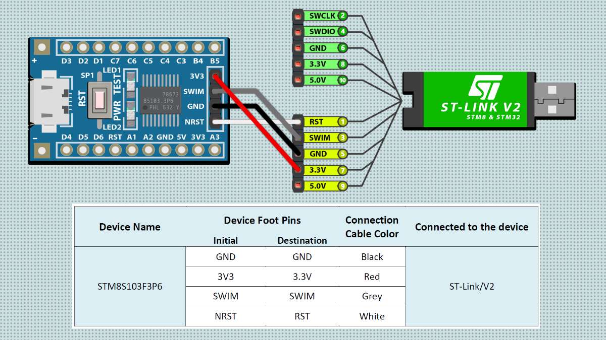
Step 7 : Wiring ST-Link/V2 to the STM8S103F3P6
Notes :
The single wire interface module or
SWIMis basically used to communicate with theSTM8board.You can see the wiring between the
ST-Link/V2and theSTM8S103F3P6board in detail in the picture above.- Based on personal experience, the
STM8can only be programmed withST-Link.
Step 8 : Removing write protection on STM8S103F3P6
The write protection on the STM8S103F3P6 board can be removed through several steps, among others :
Connect the
STM8S103F3P6board to theST-Link/V2, then connect theST-Link/V2to a PC or laptop.Open
CMD (Command Prompt).Enter into the directory :
C:\Users\[Computer Name]\AppData\Local\Arduino15\packages\sduino\tools\STM8Tools\2019.02.05\winInput the command :
stm8flash -cstlinkv2 -pstm8s103?3 -uPress
Enter, then you can see the result as the picture below..jpg)
Step 9 : STM8 (Sduino) I2C Address Scanner
/*
  =====================================================
  I2C Scanner for STM8S103F3P6
  by: Devan Cakra Mudra Wijaya, S.Kom.
  =====================================================

  Functions:
  - Detects all connected I2C devices
  - Displays device addresses in HEX format
  - Displays the total number of detected devices


  =====================================================
  SDA and SCL Pins for STM8S103F3P6
  =====================================================
  SDA -> PB5
  SCL -> PB4
*/

// Include the I2C library for I2C communication
#include "I2C.h"

// Constant that defines the delay between scans (5000 ms = 5 seconds)
const uint16_t SCAN_INTERVAL = 5000;


// The setup() function runs once when the board is powered on or reset
// It is used to initialize hardware, serial communication, sensors, modules, and the program's initial configuration
void setup() {

  // Start Serial communication at 9600 baud rate
  Serial_begin(9600);

  // Wait for 5 seconds before starting the program
  delay(5000);

  // Display program header
  Serial_println_s("====================================");
  Serial_println_s("         I2C DEVICE SCANNER         ");
  Serial_println_s("by: Devan Cakra Mudra Wijaya, S.Kom.");
  Serial_println_s("====================================");

  // Print an empty line
  Serial_println_s("");

  // Initialize I2C communication
  I2C_begin();
}


// The loop() function runs continuously after setup() has finished
// The main program logic is typically placed inside this function
void loop() {

  // Variable to store the error code returned from I2C communication
  uint8_t error;

  // Variable to store the I2C address currently being checked
  uint8_t address;

  // Counter variable for the number of detected devices
  uint8_t deviceCount = 0;

  // Display information indicating that the scan process has started
  Serial_println_s("------------------------------------");
  Serial_println_s("Scanning I2C bus...");
  Serial_println_s("------------------------------------");

  // Loop through addresses from 1 to 126
  // Valid I2C addresses range from 0x01 to 0x7E
  for (address = 1; address < 127; address++) {

    // Perform I2C write transaction (STM8 I2C driver)
    // Used to test ACK response from device
    // Error code depends on I2C driver implementation
    error = I2C_write(address, 0x00);

    // If no error occurs:
    if (error == 0) {

      // Display information that a device was found
      Serial_print_s("[FOUND] Device at address 0x");

      // If the address is less than 16:
      // Add a leading zero to keep HEX formatting aligned
      if (address < 16) {
        Serial_print_s("0");
      }

      // Display the address in HEX format
      Serial_print_ub(address, HEX);
      Serial_println_s("");

      // Increment the detected device count
      deviceCount++;
    }

    // If an unknown error occurs:
    else if (error == 4) {

      // Display an error message
      Serial_print_s("[ERROR] Unknown error at address 0x");

      // If the address is less than 16:
      // Add a leading zero to keep HEX formatting aligned
      if (address < 16) {
        Serial_print_s("0");
      }

      // Display the problematic address in HEX format
      Serial_print_ub(address, HEX);
      Serial_println_s("");
    }

    // If the error is neither 0 nor 4:
    // Ignore it, as this usually means no device exists at that address
  }

  // Print an empty line
  Serial_println_s("");

  // If no devices were found:
  if (deviceCount == 0) {

    // Display a message indicating that no devices were found
    Serial_println_s("No I2C devices found.");
  }
  else { // If at least one device was found:

    // Display the total number of detected devices
    Serial_print_s("Total devices found: ");

    // Display the value of deviceCount
    Serial_print_ub(deviceCount, DEC);
    Serial_println_s("");
  }

  // Display information about the next scan
  Serial_print_s("Next scan in ");

  // Convert milliseconds to seconds
  Serial_print_ub(SCAN_INTERVAL / 1000, DEC);

  // Display the unit in seconds
  Serial_println_s(" seconds.");

  // Empty line
  Serial_println_s("\n");

  // Wait 5 seconds before performing the next scan
  delay(SCAN_INTERVAL);
}
Step 10 : Items Counting (auto_counter.ino)
#include <LiquidCrystal_I2C.h>

#define ldrPin PD2
#define laserPin PD3
#define pbPin PD4
#define LCD_ADDR 0x27

int counter = 0;
int currentState = 0;
int previousState = 0;
int ldr = 0;
bool pushbutton = false;

LiquidCrystal_I2C(lcd, 0x27, 16, 2);

void setup() {
  Serial_begin(9600);
  device_init();
}

void loop() {
  sensor();
  reset();
  display();
}

void device_init(){
  pinMode(pbPin,INPUT);
  pinMode(ldrPin,INPUT);
  pinMode(laserPin,OUTPUT);
  digitalWrite(laserPin,HIGH);
  lcd_begin();
  lcd_backlight();
}

void sensor(){
  ldr = digitalRead(ldrPin);
  if(ldr == LOW){ currentState = 0; }
  if(ldr == HIGH){ currentState = 1; }
  Serial_print_s("\nTotal items\t: ");
  if(currentState == 1 && currentState != previousState){ counter = counter + 1; Serial_print_i(counter-1); }
  else{ Serial_print_i(counter-1); }
  delay(1000);
}

void reset(){
  pushbutton = digitalRead(pbPin);
  if(previousState != 0 && pushbutton == HIGH){
    counter = 1;
    pushbutton == true;
  }
}

void display(){
  lcd_setCursor(2, 0);
  lcd_print_s("Total items:");
  lcd_setCursor(7, 1);
  lcd_print_i(counter);
}
Step 11 : Upload Firmware to the STM8S103F3P6
Open the
Arduino IDEfirst, then open this project by clickingFile->Open:auto_counter.inoBoard Setup in Arduino IDE
Click Tools->Board->STM8S Boards->STM8S103F3 Breakout BoardChange Programmer in Arduino IDE
Click Tools->Programmer->ST-Link/V2Before uploading the program please click:
Verify.If there is no error in the program code, the next step is to use the
STM8programming tool according to the procedure. Then click:Upload.- If there is still a problem when uploading the program, then try checking the
driver/port/programmer tool/otherssection.
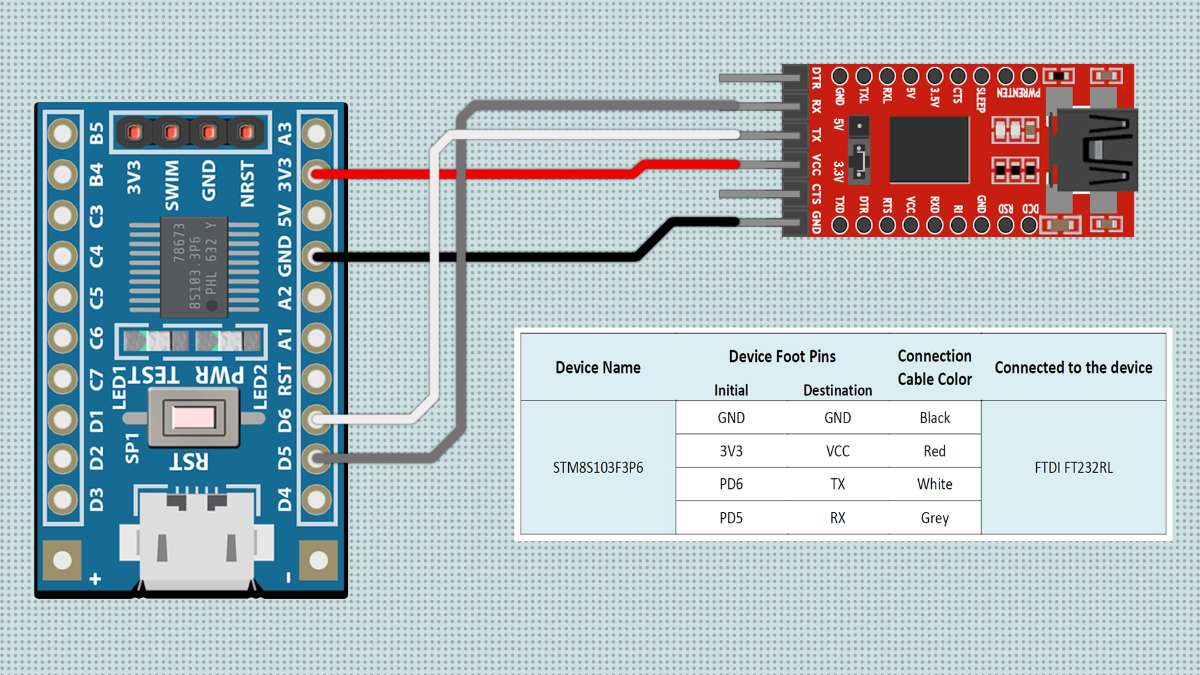
Step 12 : Wiring FTDI to the STM8S103F3P6
Notes :
Serial communication on this
STM8S103F3P6board is very possible, especially forSerial MonitorandSerial Plotterpurposes. Tools that can be used for serial communication include:CP2102 USB,CH340 USB,FTDI USB, or withPL2303 USB.You can see the wiring between the
FTDI USBand theSTM8S103F3P6board in detail in the picture above.- Based on experience, I admit that using
FTDI USBorCP2102 USBis much better thanPL2303 USBorCH340 USBbecause they are known to be more stable in performance.
Step 13 : Motor Speed Control (pwm_conveyor.ino)
// global variable initialization
#define PB1_PIN PD2 // PD2 pin to push button 1
#define ENA_PIN PD3 // PD3 pin to enable motor A
#define PB2_PIN PD4 // PD4 pin to push button 2
#define IN1_PIN PD5 // PD5 pin to rotate the motor backward
#define IN2_PIN PD6 // PD6 pin to rotate the motor forward
#define PTM_PIN PC0 // PC0 pin to potentiometer

boolean state1 = false, state2 = false; // initialize the status of digital readings on push buttons 1 and 2 into boolean data type
int pot = 0; // initialize the analog reading on potentiometer into integer data type

// Method: setup
void setup() {
  pinMode(PB1_PIN, INPUT_PULLUP);     // PD2 pin is used as an input
  pinMode(ENA_PIN, OUTPUT);           // PD3 pin is used as an output
  pinMode(PB2_PIN, INPUT_PULLUP);     // PD4 pin is used as an input
  pinMode(IN1_PIN, OUTPUT);           // PD5 pin is used as an output
  pinMode(IN2_PIN, OUTPUT);           // PD6 pin is used as an output
  pinMode(PTM_PIN, INPUT_PULLUP);     // PD7 pin is used as an input
}

// Method: loop
void loop() {
  pot = map(analogRead(PTM_PIN), 0, 1023, 0, 255); analogWrite(ENA_PIN, pot); // motor speed control with PWM
  forward(); // calling the forward method
  reverse(); // calling the reverse method
  delay(1000); // delay -> 1 second
}

// Method: forward
void forward(){
  state1 = digitalRead(PB1_PIN); // digital readout of button 1
  if(digitalRead(IN2_PIN)==LOW && state1==LOW){ // if button 1 is pressed when the motor is off then:
    digitalWrite(IN1_PIN, LOW); digitalWrite(IN2_PIN, HIGH); state1 = true; // motor rotation will be clockwise
  }
  else if(digitalRead(IN2_PIN)==HIGH && state1==LOW){ // if button 1 is pressed while the motor is running then :
    digitalWrite(IN1_PIN, LOW); digitalWrite(IN2_PIN, LOW); state1 = true; // the motor will be shut down as soon as possible
  }
}

// Method: reverse
void reverse(){
  state2 = digitalRead(PB2_PIN); // digital readout of button 2
  if (digitalRead(IN1_PIN)==LOW && state2==LOW) { // if button 2 is pressed when the motor is off then:
    digitalWrite(IN1_PIN, HIGH); digitalWrite(IN2_PIN, LOW); state2 = true; // motor rotation will be counterclockwise
  }
  else if(digitalRead(IN1_PIN)==HIGH && state2==LOW){ // if button 2 is pressed while the motor is running then :
    digitalWrite(IN1_PIN, LOW); digitalWrite(IN2_PIN, LOW); state2 = true; // the motor will be shut down as soon as possible
  }
}
Step 14 : Upload Firmware to the Arduino Pro Mini
Open the
Arduino IDEfirst, then open this project by clickingFile->Open:pwm_conveyor.inoBoard Setup in Arduino IDE
Click Tools->Board->Arduino AVR Boards->Arduino Pro or Pro MiniChange Processor in Arduino IDE
Click Tools->Processor->ATmega328P (5V, 16 MHz)Port Setup in Arduino IDE
➤ Click
Port.➤ Choose according to your device port
(you can see in device manager).Before uploading the program please click :
Verify.If there is no error in the program code, then please click :
Upload.Some things you need to do when using the
Arduino Pro Mini boardwithPL2303 USB:➤
Arduino IDEinformation :Uploading...-> immediately press theRESETbutton and release it.➤ Wait until the message appears :
Done Uploading->The program is directly operated.- If there is still a problem when uploading the program, then try checking the
driver/port/otherssection.
Step 15 : Wiring PL2303 to the Arduino Pro Mini
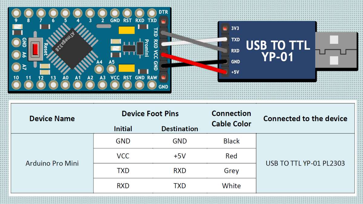
Notes :
This
Arduino Pro Miniis not equipped with aUSB port, so you need an additional device in the form of aUSB to TTL Serialto connect to a laptop or PC.USB to TTL Seriallike thePL2303 USBis commonly used as an intermediate medium for uploading programs.You can see the wiring between the
PL2303 USBand theArduino Pro Miniboard in the picture above.- To upload a program, in addition to using the
PL2303 USB, you can also use other programming tools such as:CP2102 USB,CH340 USB, or withFTDI USB. Based on experience, I admit that usingFTDI USBorCP2102 USBis much better thanPL2303 USBorCH340 USBbecause they are known to be more stable in performance.