
SCOPE OF THE SYSTEM
- The obstacles can be easily detected.
- Vehicle collisions can be avoided.
- The speed of the vehicle can be measured and intimated.
- The location of a particular vehicle can also be tracked by the concerned person.
CONSTRUCTION
STEP 1
The controller used in this setup is "Node MCU / ESP8266".
REASON FOR PREFERENCE:
*The main reason is, ‘It is very much cost efficient’.
*The programming pert is also very simple when compared to all other Microcontrollers.
*It has integrated support for the WIFI network.
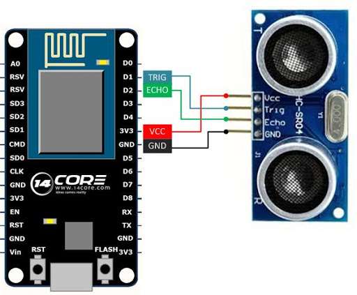
STEP 2
Connect the ultrasonic sensor
NEED
In this setup ultra-sonic sensor is used to detect the obstacles i.e. potholes and bumps on roads. It also senses the vehicle under certain distance limits. When the vehicle approaches such an obstacle with closer distance thereby alert the driver through a horn/buzzer sound.
STEP 3
Connect Accelerometer with the setup
NEED
In this setup, the accelerometer is to measure the speed of the two-wheeler. Once the speed exceeds a particular limit, it automatically intimates the registered service about the exceeded speed.
.JPG)
STEP 4
Connection of Buzzer
NEED
In this setup, buzzer is used as an output device. It is used as an indicator
.JPG)
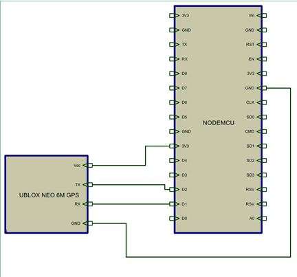
STEP 5
Connection of GPS MODULE
NEED
In this module, GPS is used to track the location of the vehicle and to share the location to the concerned people.
CLOUD
The cloud used in the implementation of the proposed system is IFTTT
REASON FOR USAGE
- Wide-ranging support – IFTTT supports some of the most popular services online.
- Ready-made applets – You might not have to use IFTTT to create a new applet.
- Free to use.
- Simplifies automation.
LISTS OF TOOLS/ SOFTWARE USED
1. Arduino IDE
Node MCU is an open-source development board and firmware based in the widely used ESP8266 -12E Wi-Fi module. It allows you to program the ESP8266 Wi-Fi module with the simple and powerful LUA programming language or Arduino IDE.
2. GPS MODULE
The software can be used on a laptop computer with an attached GPS receiver. Most commercial software runs on Windows, Mac OS X, and Linux. Some software like Waze and Google Maps can also be used on mobile phone operating systems.
PROJECT OUTCOMES
- The obstacles can be easily detected.
- Vehicle collisions can be avoided.
- The speed of the vehicle can be measured and intimated.
- The location of a particular vehicle can also be tracked by the concerned person.
APPLICATIONS
The system deserves a unique place in the market for its outstanding performance and finds its application as a default integrated system in future automobile manufacturing.
CONCLUSIONS
This safety system can widely reduce the probability of a two-wheeler accident and helps the mankind to have a safest and healthy drive.