


Basics of Current Transformer
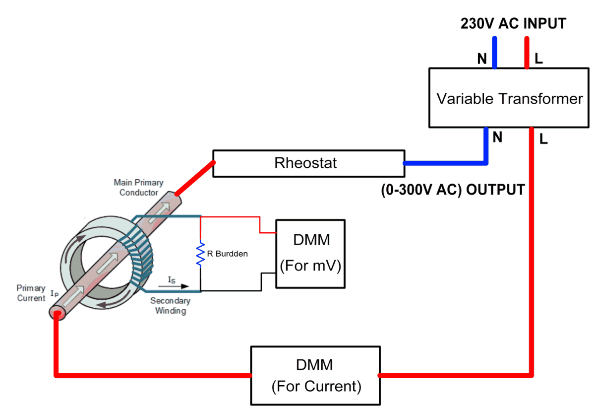
A current transformer is a device that produces a reduced current in its secondary winding accurately proportional to the current flowing in its primary winding. The secondary current flows through the secondary winding usually called as burden resistor.
Classes of CT
- 0.1 or 0.2 for precision measurements.
- 0.5 for high grade kilowatt hour meters for commercial grade kilowatt hour meters.
- 3 for general industrial measurements.
- 3 or 5 for lower accuracy commercial measurements.
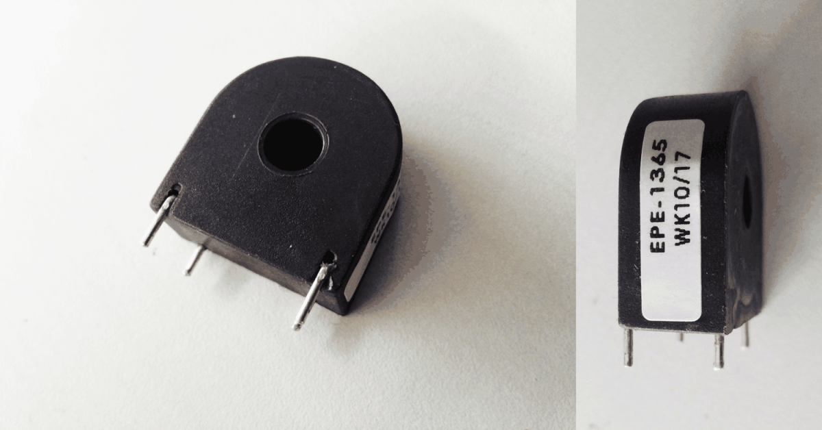
Here I’m used class 0.1 with the 2500 Turns Ratio of current transformer.
Selection of Burden Resistor
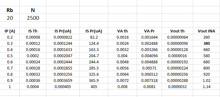
CT turns ratio is 2500:1 then the secondary current is 1/2500 of the primary current.
In a typical application, the secondary current is applied to a resistor (usually defined as the “burden resistor”) of a few ohms in order to generate a voltage signal.
Following Ohm’s law, the resulting voltage V across the burden resistor R is:
Vout=(ILoad/N)R burden
Where,
N = turn’s ratio and
I Load = primary load current.
Note: The optimum burden resistor value is specified by the CT manufacturer. If the burden resistor value is too high, the output becomes non-linear.
Selection of CT
The selection of a current transformer includes factors such as range of current being measured, turns ratio and the class. The resultant accuracy depends on these parameters. Subjecting a current transformer to load currents above the manufacturer’s rated current specification will saturate the core and may cause mechanical failures due to an excessive temperature rise. On the other hand, a current transformer that is rated much higher than the target load current might be restrictively too large and too expensive for its purpose. A typical rule of thumb is to select a current transformer which is rated approximately 20% above the expected maximum load current.
Basic Formulas
Secondary current calculation
Secondary Current (IS) = (IP/TR)
Burden VA calculation
Burden VA = IS * Rb
Output voltage calculation
Vout= (Iout/TR)/Rb
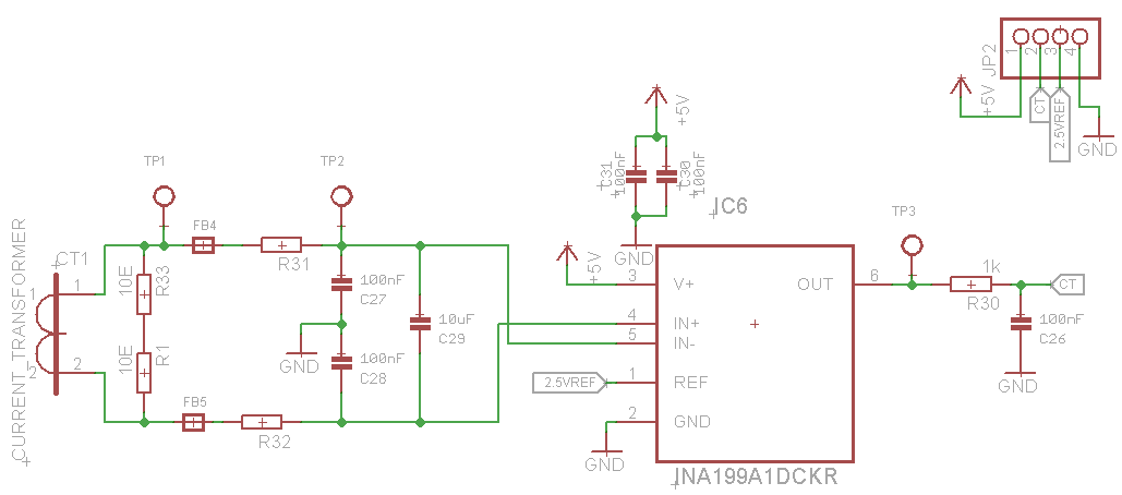
Basic Setup for CT Connection
Instrumentation Amplifier (INA199) with 100 gain:
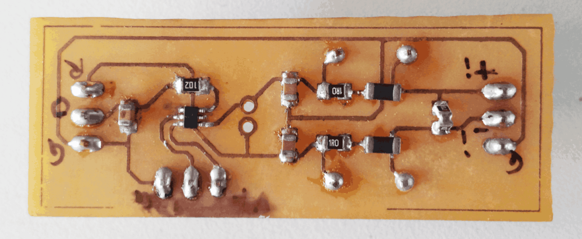
Schematic Diagram
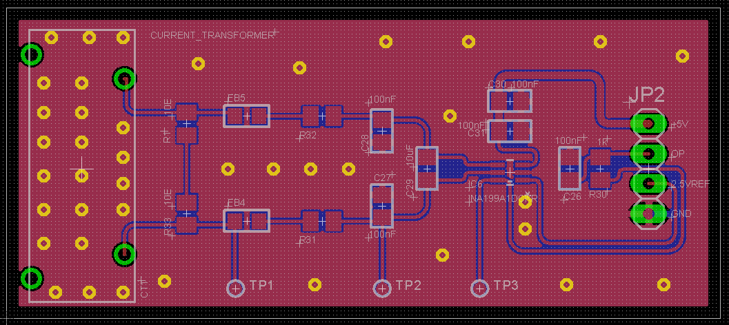
PCB layout
CT Readings